Multicast
Multicast is a “one source, many destinations” method of traffic distribution, meaning only the destinations that explicitly indicate their need to receive the information from a particular source receive the traffic stream.
Network applications that can function with unicast but are better suited for multicast include collaborative groupware, teleconferencing, periodic or “push” data delivery (stock quotes, sports scores, magazines, newspapers, and advertisements), server or website replication, and distributed interactive simulation (DIS) such as war simulations or virtual reality. Any IP network concerned with reducing network resource overhead for one-to-many or many-to-many data or multimedia applications with multiple receivers benefits from multicast.
Please refer to the Juniper Multicast Overview for more in-depth information about Multicast.
Version History
| Release | Modification |
|---|---|
| 6.1.0 | This feature was introduced |
| 6.2.0 | Added support for MSDP, SSR as RP |
| 6.2.10 | Added routing default-instance pim restart-time |
Multicast on the SSR
Multicast on the SSR supports the following protocols and topology:
- PIM Sparse-Mode
- PIM Source-Specific Multicast (PIM-SSM)
- Static Configuration of RP
- IGMP v2/v3
- Multicast over SVR in Hub and Spoke topology
Multicast Configuration
In order to support Multicast over SVR, the BGP over SVR configuration is used in conjunction with the PIM configuration to generate auto-provisioned services and service-paths. BGP over SVR must be provisioned to support the Multicast feature. See BGP over SVR for configuration details.
The following are the components necessary to configure multicast over SVR on the SSR. Configuration for each of the components is provided below, and a full example configuration is provided at the end of this process.
- Routing Interface: Specify the BGP over SVR interface
- BGP over SVR: See BGP over SVR for configuration details.
- Routing protocol such as IGMPv2/v3
- PIM
- RP: The Rendezvous Point. In the initial implementation (v6.1.x), the RP must be external to the SSR. This has been revised and the configuration below offers both configurations.
- Service: Services are created for the multicast traffic, and defined for the Group address.
- Multicast-sender-policy: Defines the tenant that is allowed to be the source of the multicast stream.
- Access Policy: Configures the tenants allowed to receive the multicast traffic via IGMP joins at routers in the network.
Refer to Tenants for more information on configuring Tenants.
Multicast Source Discovery Protocol (MSDP) is a protocol that allows inter-domain multicast communication. MSDP is only valid for the Any-Source Multicast (ASM) model. If the Source-Specific Multicast (SSM) model is used, MSDP will not send Source-Active (SA) messages to indicate an active source.
Configuration Process
The following diagram represents a simple multicast configuration. A Client sends a multicast to address 225.1.1.1. Location1 and Location2 want to receive this multicast stream. The network is setup to use an external, non-SSR Rendezvous Point (RP) at 20.20.20.20 for all multicast traffic. This router is 192.168.22.2 and is configured for BGP with SSR rtr2. It advertises 20.20.20.20 as the RP for multicast into BGP, allowing the SSR network to identify the path to the RP.
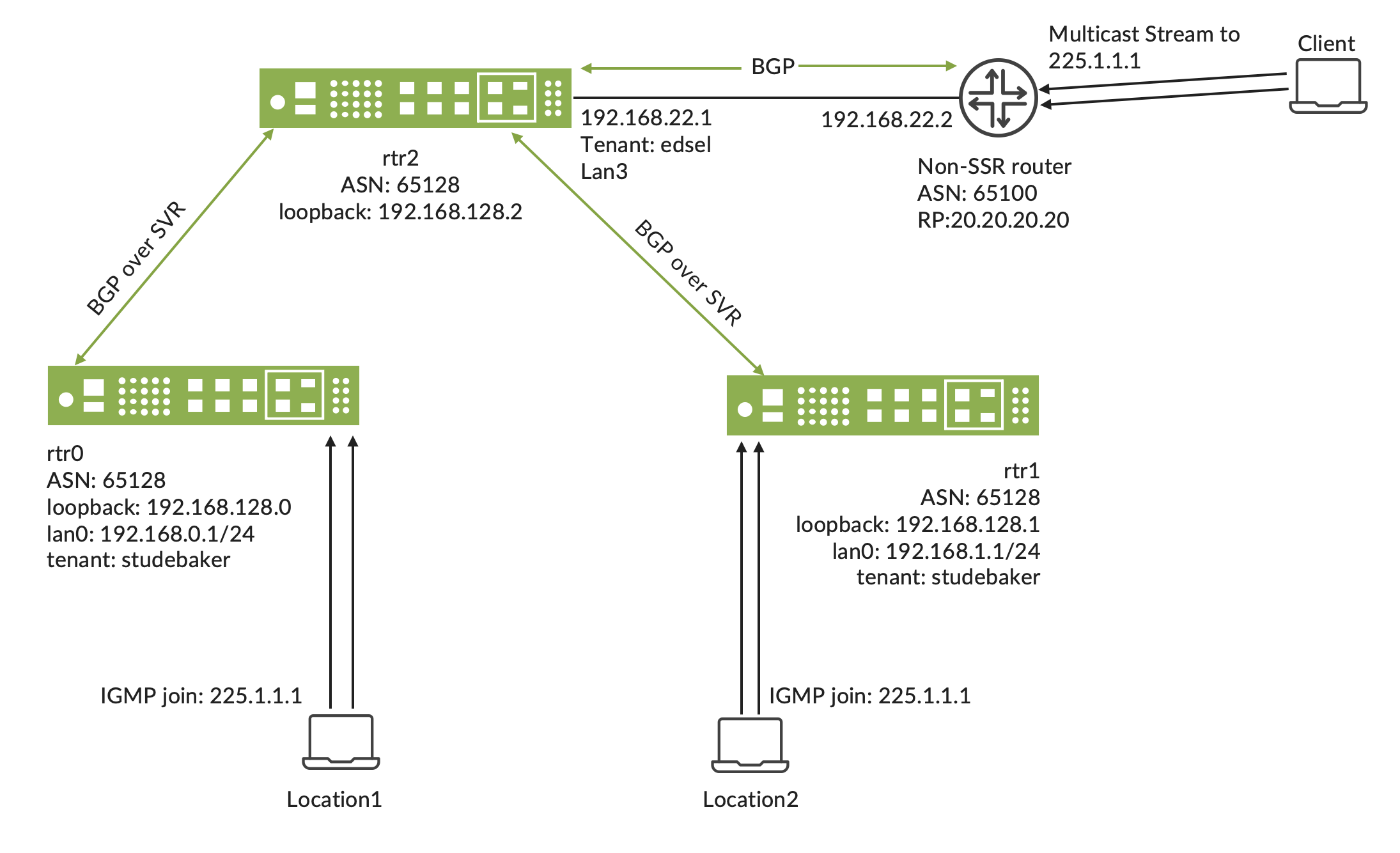
Key points in the rtr2 configuration:
- BGP is configured with the external router, 192.168.22.2
- BGP over SVR is configured with two spokes
- PIM is configured on the LAN interface towards the external router
- The tenant
edselis configured on the LAN interface
Configuration for rtr2
config
    authority
        router  rtr2
            node                 node1
                name              node1
                device-interface  eth6
                    network-interface  lan3
                        name       lan3
                        tenant     edsel
                        address    192.168.22.1
                            ip-address     192.168.22.1
                            prefix-length  30
                            gateway        192.168.22.2
                        exit
                    exit
                exit
            exit
            routing              default-instance
                type              default-instance
                routing-protocol  bgp
                    type            bgp
                    local-as        65128
                    neighbor        192.168.22.2
                        neighbor-address  192.168.22.2
                        neighbor-as       65100
                    exit
                    neighbor        192.168.128.0
                        neighbor-address  192.168.128.0
                        neighbor-as       65128
                        transport

                            local-address
                                routing-interface  loopback0
                            exit
                        exit
                        address-family    ipv4-unicast
                            afi-safi       ipv4-unicast
                            next-hop-self  true
                        exit
                    exit
                    neighbor        192.168.128.1
                        neighbor-address  192.168.128.1
                        neighbor-as       65128
                        transport

                            local-address
                                routing-interface  loopback0
                            exit
                        exit
                        address-family    ipv4-unicast
                            afi-safi       ipv4-unicast
                            next-hop-self  true
                        exit
                    exit
                exit
                pim
                    interface  node1 lan3
                        node       node1
                        interface  lan3
                    exit
                    rp         224.0.0.0/4
                        address      20.20.20.20
                        group-range  224.0.0.0/4
                    exit
                exit
To use rtr2 as the Rendezvous Point, the existing static RP configuration takes the IP address of the RP. This address should be a routable address configured on rtr2. The SSR detects this address as one of its local interfaces and assumes the role of RP. It is recommended to create a routing-interface (unrelated to BGPoSVR configuration) to be a routable address of the local RP. This routing interface must be advertised in the routing protocol. To do this either enable OSPF on the interface, or advertise the address using a BGP network command. For example:
Create the Routing Interface:
           routing      default-instance
                type    default-instance
                interface       loopback-rp
                    name        loopback-rp
                    ip-address  192.168.128.0
                exit
Advertise the Address using BGP:
               routing-protocol     bgp
                    type            bgp
                    address-family      ipv4-unicast
                        afi-safi        ipv4-unicast
                        network         192.168.128.0/32
                            network-address     192.168.128.0/32
                        exit
                    exit
Configuration for Spoke 1 (rtr0)
Key points for the Spoke configuration - this applies to each spoke, since the configuration is nearly identical.
- BGP over SVR configured to the hub
- PIM configured with the same RP on the LAN interface
- IGMP configured on the LAN interface
- Using tenant
studebakeron the LAN where the IGMP joins originate
config
    authority
        router  rtr0
            node                 node1
                device-interface  eth3
                    network-interface  lan0
                        tenant     studebaker
                        address    192.168.0.1
                            ip-address     192.168.0.1
                            prefix-length  24
                        exit
                    exit
                exit
            exit
            routing              default-instance
                type              default-instance
                interface         loopback0
                    name        loopback0
                    ip-address  192.168.128.0
                exit
                routing-protocol  bgp
                    type            bgp
                    local-as        65128
                    address-family  ipv4-unicast
                        afi-safi  ipv4-unicast
                        network   192.168.0.0/24
                            network-address  192.168.0.0/24
                        exit
                    exit
                    neighbor        192.168.128.2
                        neighbor-address  192.168.128.2
                        neighbor-as       65128
                        transport

                            local-address
                                routing-interface  loopback0
                            exit
                        exit
                    exit
                exit
                igmp
                    interface  node1 lan0
                        node       node1
                        interface  lan0
                    exit
                exit
                pim
                    interface  node1 lan0
                        node       node1
                        interface  lan0
                    exit
                    rp         225.0.0.0/4
                        address      20.20.20.20
                        group-range  225.0.0.0/4
                    exit
                exit
            exit
        exit
    exit
exit
Configuration for Spoke 2 (rtr1)
config
    authority
        router  rtr1
            node                 node1
                device-interface  eth3
                    network-interface  lan0
                        tenant     studebaker
                        address    192.168.1.1
                            ip-address     192.168.1.1
                            prefix-length  24
                        exit
                    exit
                exit
            exit
            routing              default-instance
                type              default-instance
                interface         loopback0
                    name        loopback0
                    ip-address  192.168.128.1
                exit
                routing-protocol  bgp
                    type            bgp
                    local-as        65128
                    address-family  ipv4-unicast
                        afi-safi  ipv4-unicast
                        network   192.168.1.0/24
                            network-address  192.168.1.0/24
                        exit
                    exit
                    neighbor        192.168.128.2
                        neighbor-address  192.168.128.2
                        neighbor-as       65128
                        transport
                            local-address
                                routing-interface  loopback0
                            exit
                        exit
                    exit
                exit
                igmp
                    interface  node1 lan0
                        node       node1
                        interface  lan0
                    exit
                exit
                pim
                    interface  node1 lan0
                        node       node1
                        interface  lan0
                    exit
                    rp         224.0.0.0/4
                        address      20.20.20.20
                        group-range  224.0.0.0/4
                    exit
                exit
            exit
        exit
    exit
exit
Configure the Service
The service allows the traffic to flow. It allows the tenant from the hub edsel to send the multicast stream, and the tenants studebaker on each spoke can join and receive the multicast stream.
config
    authority
        service  multicast
            name                     multicast
            address                  224.0.0.0/4
            access-policy            studebaker
                source  studebaker
            exit
            multicast-sender-policy  edsel
                source  edsel
            exit
        exit
    exit
exit
Other Considerations
While this configuration example uses one RP for the multicast range, you can use different RPs for different multicast addresses or ranges. The same can be done for the service; smaller services for more specific ranges of multicast with different senders and receivers as needed.
PIM Graceful Restart Timer
The routing default-instance pim restart-time command has been added to allow users to define the number of seconds that the PIM protocol will perform graceful-restart after a node failure. The restart time range is 0-1800, with a default of 120 seconds.
During the graceful restart period, the PIM join states are created, but no updates of multicast routes are sent to the forwarding plane. Once the graceful restart period is over, all new multicast routes are programmed, and old multicast routes are removed.
The Session Smart Router (SSR) implements PIM Graceful Restart as defined by RFC 7761. The GR protocol defines the mechanisms for populating the mroute table after a node failure. The SSR also implements a configuration parameter that controls a timer related to the overall PIM Graceful Restart behavior which expects the protocol to have fully populated its mroute table after a restart. The configuration parameter controls system behavior above and beyond the protocol graceful restart, hence it is outside of the GR protocol and is not a violation of the GR RFC.
For more information about the graceful restart timer, see graceful-restart.
Multicast Source Discovery Protocol (MSDP)
MSDP is used to allow RPs to share the active Multicast Sources. Messages are sent as Source-Active (SA) messages between MSDP peers. In normal MSDP operation, an MSDP peer is received from one peer and forwarded to the other MSDP peers. To ensure there are no loops, RPF checks have been put in place.
MSDP peer and mesh-group authentication (the auth-password parameter) uses MD5. Beginning with SSR software version 7.0 (including 7.1), FIPS mode is enabled by default and blocks MD5, so MSDP peerings configured with auth-password will fail to establish until FIPS is disabled on the affected node. See the disable procedure on the conductor install page or in Troubleshooting IDP. In a future SSR release, FIPS will be compliance-by-configuration and will no longer block these algorithms.
MSDP can also be configured as a mesh-group. In this mode, the SA messages received from a peer are not forwarded to the other members of the mesh-group, since all the peers are configured as part of the mesh. This is commonly used with Anycast RPs, where the same RP address is configured on multiple routers in the network. The Anycast RP routers use an MSDP mesh-group to distribute the active source information to the other anycast RPs. This provides redundancy in the network, in case an RP fails.
Configuration
MSDP can be configured on the router as follows:
authority
    router A
        routing default-instance
            msdp
                peer 10.10.10.2 source 16.0.0.2
            exit
        exit
Alternatively, MSDP can be configured with a mesh-group. A mesh-group is similar to an IBGP peering relationship, in that the received SA messages are not forwarded to other members of the mesh-group.
authority
    router A
        routing default-instance
            msdp
                peer 10.10.10.2 source 16.0.0.2
                mesh-group myMesh
                    source 16.0.0.2
                    member 11.11.11.1
                exit
            exit
        exit
MSDP can also be enabled in a VRF:
authority
    router A
        routing default-instance
            vrf     vrfA
                msdp
                    peer     10.10.10.2 source 16.0.0.2
                exit
            exit
        exit
Show Commands
Each of the commands listed below and the subcommands for each, provide additional details for multicast visibility. Use the links to learn more about each command.
| Command | Description |
|---|---|
| show igmp interface | Display the igmp interfaces |
| show igmp groups | Display the igmp groups |
| show msdp peer | Display MSDP peer information |
| show msdp mesh-group | Display MSDP mesh-group details |
| show msdp sa | Display MSDP source active |
| show pim mroute | Display the PIM mroute |
| show pim interface | Display the PIM interface |
| show pim join | Display the PIM Joins |
| show pim neighbor | Display the PIM neighbor |
| show pim rp-info | Display the PIM RP info |
| show pim state | Display the PIM state |
Each show command allows a vrf option:
show ip igmp [vrf <vrfname>]