Simple Network Management Protocol (SNMP) - Overview
Simple Network Management Protocol (SNMP) is an internet standard protocol for collecting and organizing information about managed devices on IP networks and for modifying that information to change device behavior. SNMP is widely used in network management for network monitoring. SNMP exposes management data in the form of variables on the managed systems organized in a management information base (MIB) which describe the system status and configuration.1
The SSR implementation of SNMP relies on the snmpd process running within the host operating system. All configuration for SNMP, however, is done within the SSR's data model via its administrative interfaces (e.g., PCLI, GUI, etc.).
MIB Definitions
SSR provides MIB files that describe the SSR SNMP objects and traps available on the SSR device and how they are encoded. For ease of use, these are installed on the device itself in this location:
/usr/share/snmp/128technology/
A Network Management System (NMS) can import these MIBs when managing the SSR appliance. The latest mibs can be optionally installed by downloading the latest "128T-mibs" package from the SSR yum repoisitory.
dnf install 128T-mibs
To install the SSR MIBS on another platform, a valid certificate and yum repo file must be present on the platform to obtain the file from the SSR repository.
The specific objects available in the MIB are described in more detail in the MIB Layout section.
SNMP v2c Basic Configuration
Configuring SNMP on the SSR is done on a per-router basis, and is done within the router > system settings > snmp-server branch of the configuration hierarchy. There are three areas of configuration required: the protocol configuration, the access configuration, and the notification receiver configuration.
Sample Configuration (Basic)
snmp-server
    enabled                true
    version                v2c
    port                   161

    access-control         my-nms-agent
        name       my-nms-agent
        community  public
        source     10.128.201.2
    exit

    notification-receiver  10.128.201.2 162 trap
        ip-address  10.128.201.2
        port        162
        type        trap
    exit
exit
Protocol Configuration
The protocol configuration requires three settings: setting enabled to true enables the SNMP agent on your SSR. Set the protocol to v2c. Finally, configure the port on which the SNMP agent will listen for inbound requests; this is typically 161, the well-known port for SNMP agent requests.
Access Configuration
The access configuration lets you create a set of "allowlist" addresses allowed to interact with the SSR SNMP agent (i.e., to send GET requests to the SSR). This represents your SNMP management platform.
The access configuration, configured within access-control in the snmp-server element, has three components:
-
name: a unique name given to the access configuration element (this is the "key" for the configuration, to uniquely identify an allowlisted SNMP source)
-
community: the community string to expect in requests from the requesting SNMP agent, as an authentication mechanism
-
source: the IP address of the allowlisted device
access-control         my-nms-platform
    name       my-nms-platform
    community  public
    source     10.128.201.2
exit
If you intend on polling the SSR device via one of the managed interfaces (i.e., one that is configured within SSR as a forwarding interface), this will require additional configuration steps. This in turn may affect the source address that the SNMP daemon sees as requests arrive. See the section below on Polling SNMP.
Notification Receiver Configuration
The notification receiver configuration defines where the SSR will send SNMP information in the event of a system issue. This is configured within notification-receiver in the snmp-server element. Like the access configuration, it too has three components:
- ip-address: the address of your trap receiver
- port: the UDP listening port on the trap receiver (typically 162)
- type: either
traporinform. This determines whether the SSR will send traps or informRequests to the receiver
Because the traps/informRequests are sent by the snmpd process running on the host Linux operating system, it is crucial that the host's routing table is capable of reaching the notification-receiver via the appropriate egress interface. Use the Linux command ip r to review the host's routing table to confirm that it meets your requirements.
SNMP v3 Basic Configuration
Configuring SNMP on the SSR is done on a per-router basis, and is done within the router > system settings > snmp-server branch of the configuration hierarchy. For SNMPv3 there are now four areas of configuration required: the protocol configuration, the view configuration, the access configuration, and the notification receiver configuration.
Sample Configuration
snmp-server
    enabled     true
    version     v3
    port        161
    engine-id   testEngineId

    vacm

        view    unrestricted
            name        unrestricted
            included    .1
        exit
    exit

    access-control  Public
        name        Public

        usm
            user-name           testUser
            authentication      sha
            authentication-key  (removed)
            privacy             aes
            privacy-key         (removed)
        exit
        view    unrestricted
    exit

    notification-receiver       172.18.0.230 162 trap
        ip-address              172.18.0.230
        port                    162
        type                    trap
        access-control          Public
    exit
exit
Protocol Configuration
The protocol configuration requires three settings:
- Set
enabledtotrue. Enables the SNMP agent on your SSR. - Set the protocol to v3.
- Configure the port on which the SNMP agent will listen for inbound requests; this is typically 161, the well-known port for SNMP agent requests. With SNMP v3, an optional
engine-idparameter is available, to uniquely identify the SNMP engine.
View Configuration
The view-based access control (VACM) configuration is used to define a list of views which serve as the mechanism to allow or restrict which OIDS a user may have access to. Each view has three components, and one hidden component:
- Name: the view name
- Included: a list of OIDS which are allowed
- Excluded: a list of OIDS which are not allowed
- (hidden) Strict: This is a hidden field. A boolean that defines the use of strict mode when parsing the include and exclude lists. It is set to true by default.
Strict Mode
Strict mode is enabled by default. The SSR publishes a set of MIBS that define the OIDS available to query and evaluates the include and exclude lists to ensure each OID exists in the available SSR MIBS. If they are not, the configuration is rejected. This serves to restrict the NMS from querying OIDS that may be supported by the underlying operating system of the SSR.
Support of system MIBS may vary between SSR versions. Bypassing these checks by disabling strict mode may allow access to MIBs that are no longer supported. Disabling Strict mode is only recommended for advanced users.
Access Configuration
With SNMPv3 enabled, access configuration allows you to define a User-Based Security Model (USM) as per RFC 3414. The access configuration is configured from within access-control in the snmp-server element, and has three components:
- Name: Unique name given to the access configuration element (this is the key for the configuration, to uniquely identify an allowlisted SNMP source)
- USM: The user based security model settings
- User-name: Name given to the user
- Authentication: Authentication protocol to use (MD5 or SHA)
- Authentication-key: Authentication password
- Privacy: Encryption algorithm (DES or AES)
- Privacy-key: Encryption password
- View: Restrict user access to the pre-configured view
Authentication and Encryption
The SSR combinations of authentication and privacy as defined in the USM configuration are translated into an SNMPv3 security level:
- noAuthNoPriv: When both authentication and privacy are set to
None - authNoPriv: When authentication is set to either MD5 or SHA, but privacy is set to
None - authPriv: When both authentication and privacy are set to anything other than
None
These security levels are necessary when performing SNMPv3 operations, and the NMS is responsible for mapping the SSR USM configuration to these security levels.
Notification Receiver Configuration
The notification receiver configuration defines where the SSR sends SNMP information in the event of a system issue. This is configured under notification-receiver in the snmp-server element. For SNMPv3, there are four configuration elements:
-
ip-address: Address of your trap receiver -
port: UDP listening port on the trap receiver (typically 162) -
type: Trap or Inform. Defines whether the SSR sends Traps or Inform Requests to the receiver -
access-control: References the pre-configured access-control to use, identifies which configured user should handle the notifications, which ensures the appropriate authentication and encryption are used for the communication.
Because the traps/informRequests are sent by the snmpd process running on the host Linux operating system, it is crucial that the host's routing table is capable of reaching the notification-receiver via the appropriate egress interface. Use the Linux command ip r to review the host's routing table to confirm that it meets your requirements.
Traps vs Informs in SNMPv3
The use of the engine-id parameter is specific to SNMPv3 and traps/informs. SNMP protocol dictates that for traps, the sender (in this case, the SSR) is authoritative, which is to say, the engine-id in use by the SSR will be placed in the messages, and that the companion NMS software will need to define the USM for the sending user with the engine-id of the SSR. In the case of net-snmp being the NMS, the following is an example of how to define SNMPv3 users. This would be placed in the snmptrapd.conf configuration file:
createUser -e <hex encoded engine ID in use by net-snmp on the SSR> testUser SHA password1 AES password2
In the case of Informs, the NMS is authoritative. In this case, the inform message passes along the engine-id of the NMS so that the SSR automatically uses it when sending responses. The SSR will not need to be configured with or have pre-shared knowledge of the engine-id of the NMS.
Polling SNMP
Once the snmp-server is configured, the SSR device is eligible to be polled for SNMP requests from any source identified in an access-control configuration. Depending on your system architecture, this may require some additional configuration for polling to be successful.
Routing SNMP Responses
Because the SNMP protocol is handled by a system process running on the host operating system, it is important that your host operating system's routing table has routes suitable for returning responses to inbound queries to the appropriate destination(s) via the appropriate interface. Use the Linux command ip r to review the host operating system's route table, to ensure that snmpd is capable of transmitting responses to inbound polling requests.
This also applies to traps sent by the SSR to the notification-receiver.
When sendiing responses via a forwarding interface (as described below), the SSR software manages the Linux routing table rules on your behalf.
Polling via Forwarding Interfaces
A forwarding interface is one that is identified in your SSR configuration as being managed by the SSR software – generally, this is a device-interface of type ethernet, with a pci-address on your platform's PCI bus. In order to successfully poll an SSR via a forwarding interface, there are several other configuration components required:
- A
host-serviceon the network-interface, with type set tocustomandtransportset to UDP/161 (or whichever port you've specified in yoursnmp-serverconfiguration). - The
host-serviceshould include one or moreaccess-policystatements to allow access by the SNMP polling device(s). - The
access-controlin thesnmp-servershould have itssourceset to169.254.127.126instead of the actual address of your SNMP polling server. This is due to the fact that the inbound SNMP requests will arrive at the Linux host operating system via a kernel network interface (KNI), which performs source NAT of the outbound packets sent to snmpd.
Sample Configuration (Via Forwarding Interface)
snmp-server
    enabled                true
    version                v2c
    port                   162

    access-control         snmp-agent
        name       snmp-agent
        community  public
        source     169.254.127.126
    exit
exit

network-interface
    name                   lan
    description            "LAN"

    inter-router-security  internal

    address                192.168.1.1
        ip-address     192.168.1.1
        prefix-length  24

        host-service   custom
            service-type   custom

            transport      udp
                protocol    udp

                port-range  161
                    start-port  161
                exit
            exit

            access-policy  10.128.201.2/32
                source      10.128.201.2/32
                permission  allow
            exit

            access-policy  blocklist
                source      blocklist
                permission  deny
            exit
        exit
    exit
exit
MIB Layout
The SSR MIB Database tree is structured as shown in the following diagram:
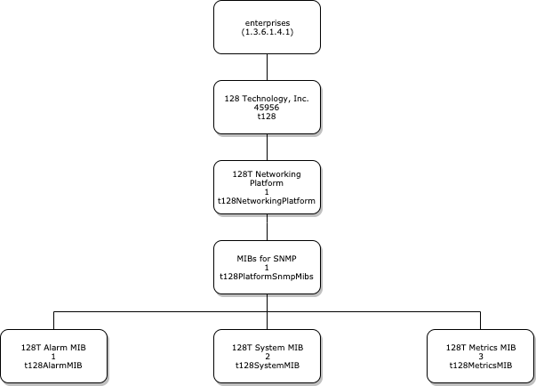
Note that the SNMP MIB objects only support read-only access (eg: GET, GETNEXT). To configure or alter the system, use the PCLI, Web GUI, or configuration APIs (e.g., NETCONF).
The
netconfconfiguration API is not applicable to version 5.3 and later. NETCONF controls have been replaced with REST API controls, with no loss of functionality.
The MIBs are described individually below.
T128-MIB.mib
The parent T128-MIB defines the overall structure of the MIB and supported products. Only the t128NetworkingPlatform currently exists, however future MIBs may expand this to other SSR products.
T128-ALARM.mib
The T128-ALARM-MIB defines objects that describes the state of SSR alarms. The MIB also contains definitions for the SNMP trap notifications sent out by the system on event of an alarm being added or cleared.
There are two tables for viewing the current alarm state, t128AlarmTable and t128ShelvedAlarmTable. Each row in this table represents a unique alarm that is active in the system. The t128ShelvedAlarmTable represents alarms that are shelved (for instance if the router is marked as being in maintenance-mode). The t128AlarmTable represents current alarms that are active and not shelved. The key for each row is an instance identifier string, either t128AlarmTableInstanceId or t128ShelvedAlarmTableInstanceId depending on which table the alarm resides. This string can be used to indicate a specific instance of an alarm, for example "Interface operationally down on eth0", which would be a different instance than a "Interface operationally down on dpdk1" alarm. This instance identifier should be considered an opaque string (i.e. the contents have no meaning other than that for each alarm this string is garaunteed to be unique).
The opaque instance identifiers are currently implemented as hex strings however the implementation may change from release to release so the exact content should not be relied on.
The t128AlarmNotification definition defines the alarm trap sent out by the system and contains the relevant objects to describe the alarm (e.g. source node and router, severity, alarm message, etc). The trap will also contain a unique t128AlarmInstanceId that can be used to correlate the alarm with the t128AlarmTable and t128ShelvedAlarmTable instance identifiers. If an alarm moves from a shelved to unshelved state or vice versa the instance ID will remain the same.
T128-METRICS.mib
The T128-METRICS-MIB provides SNMP access to the expansive set of metrics provided by the SSR product which are exposed via the t128MetricsTable.
Each row of the metrics table is keyed by two objects, the t128MetricAlias and the t128MetricIndex. The t128MetricAlias is an arbitrary string up to 64 characters long that represents a description of the metric. When read from the table, this alias also includes a metric instance suffix which in the most common case will be _0. For example, if the default CPU utilization metric has an alias cpuUtilization, it will be returned as cpuUtilization_0. In addition to the alias, the t128MetricIndex key represents a unique series of a metric.
The values contained in each row are the t128MetricValue and t128MetricContributors objects. The t128MetricValue is simply the current value of the metric. The unique parameters that identify each data series are referred to as "contributors". For the CPU metric, the contributors are router, node, and core. The t128MetricContributors object will contain a string representation of these values so that each row can be correlated with the correct metric data series.
Below is an example of an SNMP query of the t128MetricsTable showing the 4 rows returned for each CPU utilization data series:
snmptable -Cl -Ci -mALL -v2c -c public 172.18.1.55 T128-METRICS-MIB::t128MetricsTable

SNMP table: T128-METRICS-MIB::t128MetricsTable

index                   t128MetricContributors    t128MetricValue
"cpuUtilization_0".0    Fabric128.test1.3         5
"cpuUtilization_0".1    Fabric128.test1.2         2
"cpuUtilization_0".2    Fabric128.test1.1         100
"cpuUtilization_0".3    Fabric128.test1.0         4
Note that in this example the router name is "Fabric128", the node is called "test1" and the CPU cores are 0, 1, 2 and 3. This can be clearly seen in the t128MetricContributors column, eg: "Fabric128.test1.0".
The metrics table can be configured to contain any of the SSR metrics that can be exposed via SNMP however this is an advanced feature and is outside the scope of this document. By default a small set of the most useful metrics are configured in the t128MetricsTable.
T128-SYSTEM.mib
The T128-SYSTEM-MIB contains objects to describe the running state of the local SSR system.
The local node and router name, role and asset-id objects (t128RouterName, t128NodeName, t128NodeRole and t128AssetId) can be used to identify the system. The values of these parameters will match those in the SSR system configuration.
There are several processes running on the system that comprise the SSR product. The table t128ProcessTable provides details about these processes, for instance whether they are running or, if applicable, are assuming a leadership role. The key for the table rows is the process name, for example "nodeMonitor".