SD-WAN Design Guide
Abstract
This guide is intended to provide a consistent methodology for approaching new customers, to establish a high-level design (HLD) for an SD-WAN solution.
Introduction
This document will provide the outline for a process to design an SD-WAN solution. The document will begin with simple, high-level elements before expanding upon each of them.
All efforts should be made during the design phase to design a simple, consistent network. This will pay dividends during the steady-state operation of the network, as it will greatly facilitate troubleshooting and diagnosis.
The SSR solution provides a very flexible framework for delivering services across a network. This document does not attempt to show all possible design options, but rather to present many best current practices for SD-WAN based on existing deployments. It is intended to ensure the architect considers many important design choices when constructing an SD-WAN service. In many deployments, there will likely be items not covered in this design guide.
Lastly, this document is designed to function as a reference. A linear read through of this document and translation to design will likely not be possible, as options presented in one section may impact choices made in previous sections. Ultimately, the high level design will likely require an iterative approach with multiple passes through these sections until, ultimately, all stakeholders are happy with the full architecture.
High Level Investigation
This section defines topics of data gathering that should be investigated with the customer at the kickoff of the project. These items will directly feed into design considerations for the deployment.
Define Site Types
A typical SD-WAN deployment consists of sites that can generally be considered as "branch" or "data center." Oftentimes, though, deployments can be more complex. For example, an enterprise may have different categories for branches that service different business functions and must be considered separately during the design process. Likewise, different data centers may host different applications and therefore warrant individual discovery, whereas georedundant/disaster recovery data centers should ideally be members of a single site category.
This list should be short with a minimal number of categories as the more variation, the more difficult the network is to manage. However, this will likely depend on the reality of the current customer deployment and any constraints from the end customer.
While the goal should be to have all sites of the same category share a design, small variations in sites should not necessarily require a new category and can be handled in design. For example, in a retail store deployment where some locations may get access to different services or contain different LAN networks, but the baseline architecture is the same, we can handle this as a single category (please note known variations in the comments).
The number of sites that fit each category should be noted, as well as a rough idea of the maximum throughput required for these sites. This information will inform hardware selection. Please account for any planned growth in this throughput number to ensure sufficient hardware is selected at the outset, to avoid a future hardware replacement.
Any distinctive aspects of the site category should be noted. For data centers, note the category of applications that are hosted there. Any known requirements integrating into the existing network infrastructure (i.e., the IGP used such as BGP or OSPF) should be noted. If any sites are cloud-based, this should be noted. If the SSR routing function is intended to be virtualized (run in a virtual machine) at any sites, this should be noted along with the hypervisor required at the site.
Another note to make while enumerating site types is whether or not the site will require redundancy of the SSR. There are several design options for achieving redundancy, each of which will be discussed later in this document; however, all of them require an additional device running SSR software. In some cases customers may opt for a non-redundant design, particularly if logistics and field services teams can replace components within an acceptable window of time. Other customers may view any downtime as unacceptable and opt for a redundant design in all sites. Data center sites almost always have some form of redundancy due to being an aggregation site for traffic from multiple branches.
Define Applications
Networks exist to deliver applications and services. Make a list of the applications the customer needs to deliver to these sites in order to conduct their business. For a retail store deployment, common functions are point of sale, inventory management, and voice services. The customer likely has their own names for these applications and every attempt should be made to use their vocabulary – referencing these names in the SSR data model makes them appear in output of show sessions, show load-balancer, charts in the GUI, etc. During the deployment, if a branch is having a problem with one particular application and calls to request assistance, the name of the application that the branch personnel is calling about will be readily identifiable.
When identifying applications with the customer, be sure to also probe for low level services required to deliver these applications. Services such as DNS, NTP, LDAP, etc should be accounted for as the business applications likely will not function without these basic network services.
For each application, be sure to note which site categories will initiate the application traffic (source) and which site categories will terminate (destination) the traffic for the application traffic. If sessions for this application are initiated bi-directionally, this should be noted as well. Be sure to note the business purpose of the application, if this is not already clear. This will help in the future during troubleshooting
Be sure to include general internet access, as this is often overlooked but needs to be defined as a service in the SSR data model. Please note whether the customer intends to backhaul internet traffic to a data center for security filtering or if they desire local breakout of internet. If local breakout is required, does this traffic need to pass through any local security devices first? Or does the customer have a cloud-based security stack they wish to leverage? If multiple "internet" services (such as one for a segmented unsecured wifi network) exist, please enumerate those as well.
Any services that need to traverse between sites of a particular category should be noted ('branch to branch services")', as should any services that need to traverse between networks within the same site ("intra-site services").
And finally, does the SSR need to provide any direct services to clients such as DHCP server or DHCP relay?
See also: Application Discovery
Define Client Segmentation
Now that applications have been defined, we need to define the categories of source traffic that will consume these applications. In the SSR data model, tenancy can be used for segmentation of traffic, providing security by only allowing appropriate access to the defined applications. It is important to work with the customer's security team to understand their vision for allowing/restricting access to specific applications. Typically, in the SSR configuration, a tenant is most closely associated with a particular vlan that applies to multiple sites. For example, a point of sales VLAN across all branch sites can ensure that point of sales traffic is locked down for PCI requirements.
Define Transport options
A typical SD-WAN deployment has two or more WAN connections per location. These options typically include broadband internet connections, LTE connections, and MPLS connections. Enumerate the number of options per site category (for example, if some sites plan to have multiple broadband interfaces, please indicate each broadband option for that site category). Make note of address family that is required on the transport: IPv4, IPv6, or dual-stack configuration. Make note of the method used to obtain an IP address: static configuration, DHCP, or PPPoE. This may change site-by-site across a site category, but all potential options should be included. Note whether a NAT device is expected between the site and other sites (private IPv4 address on broadband, LTE CGN, etc). Note whether the transport will have outbound connectivity to the internet (likely for all but MPLS and some private LTE APNs). Any requirements for connections options other than Ethernet or supported LTE hardware should also be noted (T1, LTE USB dongle, etc).
High Level Design
Conductor Design
Main article: Conductor Deployment Patterns
The conductor functions as the centralized management node for the deployment. All routers connect to conductor in order to receive configuration updates and all network operations personnel connect to conductor to manage the network. The conductor must be reachable by all SSR nodes within the authority. There are several popular options for conductor deployment. Often, the MSP will host the conductor in their own data centers where they also provide services to the end customer. At other times, public cloud instances are used for a deployment. If the end customer requires direct access to the conductor, it may also be placed in one of the customer data centers, however details of accessing this conductor for the MSP partner will need to be worked out.
The SSR conductor supports high availability and the two nodes in an HA conductor can be placed in different locations. However, it is essential to provide reliable, low-latency, low-loss connectivity between these two nodes. Frequent drops in connectivity between conductor nodes can result in synchronization issues. If the conductor is deployed in a public cloud environment such as AWS, it is suggested to place the nodes within the same region and same vnet but in different availability zones for redundancy.
The SSR conductor can be placed directly on the internet and protected with firewalld, or it can be placed behind a firewall. It can be placed behind an SSR edge router at a data center and exposed as a service in the SSR data model, though this adds complexity to the design and is generally not best practice. In scenarios where the conductor is placed behind an SSR edge router, the conductor communication must use standard routing and not SVR to pass through the edge SSR.
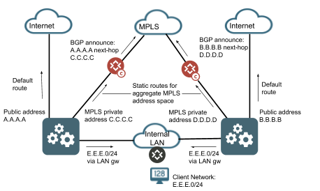
The SSR conductor is a standard Linux system and supports multiple interfaces. For example, you can configure your conductor instance with an interface connected to the internet, an interface connected to a private internal network, and an interface connected to your MPLS network. However, the router itself does not understand multiple IP addresses for the same conductor node. You can provide a backup path to your conductor over your MPLS network by advertising the public, internet addresses for conductor that are assigned to the router into the MPLS network and setting the next-hop as the private MPLS IP of the conductor node. The Linux OS will handle this and provide availability to conductor over the MPLS network allowing an additional service-route to conductor over this transport. It is up to the network operator to ensure all appropriate Linux static routes are configured to allow return traffic to flow out the appropriate interface when leveraging multiple interfaces for conductor. An example of a multi-interface conductor architecture is shown below for reference.
Pod Design
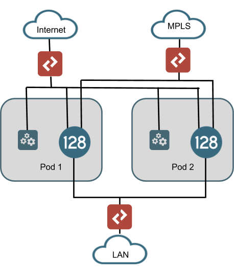
As of the writing of this document, the SSR conductor can manage roughly 2,000 routing nodes (or 1,000 highly available routers), with appropriately sized hardware. While this number continues to grow with improvements in software, there will always be a threshold where partitioning of the network needs to occur. The current solution for dealing with deployments that exceed this number is to leverage pods. A pod is a conductor instance, data center routing instances, and all branch instances that communicate with these conductors and data center routers. The drawing below shows an example of a data center architecture with multiple pods where each pod has a unique conductor and data center router. These conductors and routers in different pods do not communicate, but should be configured the same way so that any branch can be assigned to any pod and provide the same functionality. In this manner, each Pod is autonomous from the others. Therefore, if branch-to-branch communication is a requirement of the deployment, consideration must be made for how traffic from one branch can exit Pod 1's head end router and enter Pod2's head end router.
There are many considerations with a pod design. In the drawing above, the handoff to the LANs is shown as an L2 switch. However, if BGP is to be used, it may make more sense to implement an aggregation router in order to provide a single BGP handoff on the LAN router or to the MPLS PE router. This would likely be a requirement for handling branch-to-branch communication across Pods. Additionally, a multiple pod architecture imposes other resource requirements such as switch port capacity, IP address utilization, rack space, and power that need to be considered.
Tenancy Design
Main article: Tenancy Design
From the discussion with the end customer on segmentation, the definition of tenants should be relatively straight forward. The goal is to create a list of global profiles that can be used for access policies to services. Conceptually, tenancy should not be tied to a location and should be a global construct available whenever we want to classify traffic to a profile when it enters the SSR fabric across the authority (though at times due to business logic defined by the customer, a tenant may reflect a location). At any point in the authority, when traffic ingresses into an SSR, tenancy is applied. Typically this is done by assigning the tenant to the network-interface according to the purpose of the VLAN for which the SSR is the router. For example "POS" for point of sale, "voice" for telephony devices, and "core" for traffic coming from the customer's core network (if no further breakdown of tenancy is required for this traffic). The SSR can also restrict ingress traffic into a tenant further by creating a neighborhood on the network interface. Neighborhoods serve multiple purposes and an additional discussion of neighborhoods will occur in an ensuing section. In the global tenant configuration, this neighborhood may be referenced as a "member" and then CIDR block ranges for source addresses can be defined within this member. In this manner, a shared neighborhood name can be configured on a common LAN network for a site category and the tenant configuration can be updated with the specific list of CIDR ranges that will be used to identify which source IP addresses belong to a particular tenant for traffic coming in on this interface.
Tenancy information is conveyed between SSRs through metadata in Secure Vector Routing. Because of this, a router may apply appropriate next-hop service routing for traffic from a particular tenant even if it has no interfaces configured to classify traffic to this tenant.
The SSR data model supports hierarchical tenants. In this model, access policies of the parent tenant are inherited by the child tenant, but not vice versa. This can allow for simplified access policies in many cases. A child tenant is declared by naming the tenant with a dot (".") such as "child.parent". One suggested model for hierarchical tenant naming would be "<vlan role>.<site category>.<enterprise>". This would allow for simplified access policies for services that should be accessible for all tenants within a particular site category and also for all tenants that fall within the enterprise. Tenant hierarchy is not a requirement and is only suggested for use when it simplifies a deployment.
Service Design
Main article: Service and Service Policy Design
Service design is the heart of the SSR configuration. Services can be configured using IP addresses, hostnames, CIDR block ranges, and optionally transport protocols and specific ports. A service can be configured as generally as address 0.0.0.0/0 for the entire IPv4 address space or as specific as an individual /32 address and a single UDP or TCP port. These service configurations result in entries in the FIB table, which is what the SSR uses to make forwarding decisions. In order for any traffic to pass through an SSR, its source must be classified as belonging to a tenant, its destination needs to match a FIB entry for this tenant, and a next-hop must be available for this service traffic (more on this in the next section). If there are multiple service definitions that match the destination traffic for a tenant, the router will choose the most specific. Be careful, though, because a service configured with address 0.0.0.0/0 and a single port is considered to be more specific than a service configured with a /32 address and no port defined. Services that apply to different tenants can have the exact same definition and be given different treatment. For example, "Gold", "Silver", and "Bronze" users can be assigned to different tenants and each have an "internet" service with address 0.0.0.0/0 but each can be configured to assign the traffic to a different traffic engineering classification, or can be routed out via different interfaces.
It is suggested that during the testing phase in the customer lab a large effort be put into understanding the details of these services down to all traffic flows required for the full service functionality. Using wireshark to capture traffic on the LAN during this testing is suggested. The customer should perform all tasks relating to the application while packets are being captured including restarting the application, logging on to the application (if applicable), and performing all tasks related to the application. The application owners within the IT organization at the customer should be consulted with to investigate their knowledge of IP addresses, ports, and protocols used for the application. Any existing firewall rules used for the application can be of service with this exercise as well.
Also, while performing this application investigation, be aware of the timeout values for sessions. Since the SSR is a session-aware router, it uses timers to indicate the maximum idle time for a session before it removes that session from memory. There are many pre-configured session-types in the SSR configuration that use a standard value. If traffic comes in that does not match a specific session-type, the SSR will use default timers. For UDP sessions, the default is 180000ms (three minutes) and for TCP sessions, the default timer is 1900000ms (roughly 31 minutes). If the customer's application establishes a TCP socket that remains idle (without any keepalives) for longer than this value, the SSR will remove the session from the session table. The next PDU that is attempted across this socket will receive an RST from the router (assuming transport-state-enforcement is set to the default "reset" in the service-policy). This may result in a poor experience for the customer, as a user may receive negative feedback from the application (e.g., "Connection lost!"). Creating custom service-type configuration for this traffic and setting a larger timeout value will solve this problem.
There does not need to be a 1:1 ratio of customer defined applications to service definitions. For example, "voice" may be defined as an application. But for many reasons it may be desirable to create services for both the SIP and RTP protocol flows that make up the voice application. Also, dividing the service definition address space between data centers may be important if using service-routes to direct traffic (more details in the next section). Therefore, in this example, one customer defined application would result in four configured services.
While performing service design, give thought to service-policy options that need to accompany each service. For example, if the customer has a transport with class of service such as MPLS, they may prefer to send sessions for specific services over MPLS than broadband. Whereas applications deemed less critical may need to prefer broadband. If session migration needs to be allowed, it must be enabled in the service policy. If that migration needs to take path SLA into account, that must be enabled in the service policy and the SLA requirements can be customized in the service policy as well.
Many times, the customer may have an accelerated timeline and wish to deploy without doing a full service investigation. In this case, it is recommended to create services at a minimum which enumerate the complete set of address space their branches need to reach in each data center. Over time and as needed, additional service definitions can be created as the details of the customer's services are discovered.
One larger consideration for a large deployment is FIB size. FIB entries consume memory resources on the router. One way to avoid this is to avoid creating FIB entries where they are not needed. If a service does not apply to all routers in the configuration, we should restrict it to apply only where it is needed. We can do this by creating router groups. In the first portion of this document, one item was to enumerate the applications used by the customer and to indicate the site categories that used the services, either as the source or destination. These site categories can be used to create router groups, which is a label we can apply in config to any router that fits within this category. In our service configurations, we can configure an applies-to setting that indicates the particular router groups to which it should apply.
Routing Design - Service Routes
The SSR allows for routing on more criteria than simply L3 address. Routing decisions can be made based on the services that network operators define, which includes transport protocols and port ranges. As mentioned in the section on service design, in order for any traffic to pass through an SSR, its source must be classified as belonging to a tenant, its destination needs to match a configured service to which this tenant has access, and a next-hop must be available for this service traffic. This section attempts to provide details of where those next-hops come from.
The SSR data model introduces an element called the service-route. The service-route is effectively a mapping of a named service to next-hop decisions for traffic that matches this service. There are essentially two kinds of service-routes. A static service-route will tell the router to egress traffic via traditional IP routing (non-SVR) out an interface. A peer service-route tells the router that this traffic is destined for another SSR using SVR. This service-route does not directly dictate any particular path to reach the remote router. This decision is made by the router based on the configuration of the adjacencies to this remote peer, their vector configuration, and the configuration found in the service's service-policy.
In the absence of any configured service-routes, the SSR will look at its RIB to make a next-hop decision. This can often result in some non-intuitive results. For example, if a network operator desires to allow a tenant access to an internet service, they will typically define a service with address 0.0.0.0/0. If there is no service-route configured, the RIB will automatically cause FIB entries to be created for any directly connected networks. This is often against the desire of the operator who wishes to use services and tenancy to restrict access to certain VLANs. This situation can be solved by using a service-route to direct traffic that matches the internet service out the WAN interfaces. With this configuration, clients that attempt to access addresses in a network that is directly connected to the router will have this traffic routed out the WAN - absent a more specific service that allows them access to this network. An alternative configuration that doesn't use a service-route to achieve this goal would be to create a service or services that match the address space of the directly connected networks we want to block and then to create an access-policy for this tenant that has the permission set to deny.
The RIB consists of directly connected routes for any configured interfaces, explicitly configured static routes, and routes learned via dynamic routing protocol. Configuring a gateway on a network-interface does not result in a RIB entry.
If any service-routes are configured for the service in question, they will override any data from the RIB - even if these service-routes are currently unavailable.
Outside of a peer service-route, there is one mechanism that will allow traffic between SSRs over SVR - BGP over SVR. BGP over SVR sets up a BGP peering relationship between loopback interfaces on each router. The SSR conductor will automatically create a BGP listener tenant and a BGP service for each router's loopback address. The routers will use any available peer paths for the BGP traffic (this can be changed by configuring a service-policy in the auto-generated BGP service and setting the generated flag to false). Any routes learned from the SSR BGP peer will be inserted into the RIB. If traffic matches a FIB entry that uses this RIB information for a next hop, that traffic will be sent over SVR to the SSR peer. The traffic for this service will be influenced by that service's specific service-policy (i.e. it will use the correct peer path vectors configured for that service and not the BGP service).
Because of this, BGPoSVR provides some interesting advantages. Not requiring a peering service-route to get traffic to a specific SSR peer also means that for traffic initiated from data center to branch, we do not need a unique service for each branch site. We can, instead, create an aggregate service that contains all possible branch address space. Configuring each branch SSR to advertise its local network using BGPoSVR causes the data center router to create appropriate RIB entries to each peer's loopback. Taking this further, more specific branch services can be configured using the same address range and the specific protocol and port ranges of the service. This allows us to send these services over different vector priorities. For deployments with a large number of branches where we want to treat prefer different WAN transports for different traffic from data center to branch, this greatly helps us reduce the size of configuration.
However, the lack of service routes when using BGPoSVR does introduce some additional scenarios to be aware of. The explanation earlier in this section about how lack of service routes can lead to some non intuitive behavior when using an internet service also holds true here. If there is an internet service or similar where the routes are learned by BGPoSVR and this overlaps with directly connected networks in the branch - or even address space of other branches - source tenants with access to this service will have access to these directly connected networks and networks in other branches (through the head end router). In order to avoid this, a "deny" service can be created using the aggregate branch address space just like in the example above, but by setting the tenants in the store to have an access-policy with permission "deny". This will block inter-network traffic within the branch and also branch-to-branch traffic. A more specific service definition can be created for any particular protocol and port ranges that need to be allowed between networks or branches.
Another non intuitive scenario exists with BGPoSVR and learned routes. If the learned routes overlap with the destination addresses of remote adjacencies, there is a chance that a change in the routing table will cause the SSR to attempt to send BFD traffic over the BGPoSVR connection, which will result in the peer paths being taken down. If any routes are advertised which overlap with remote waypoint addresses, it is advised to configure a static-route to the remote waypoint out the WAN interface(s) that can reach them. This will provide a more specific route in the RIB for BFD and SVR packets that will avoid this routing convergence.
One design consideration to keep in mind when using BGPoSVR is that for services that leverage these learned routes, a service-route should not be used as they will override the learned routes. This is most applicable to scenarios where breakout internet is preferred to be sent out of the branch as local break out with a fallback path to the data center through a learned default route (for example, if the alternative transport at the branch is MPLS, we can reach the data center SSR over MPLS and allow the data center to route this traffic out to the internet as a fallback mechanism). In this scenario, a service-route should not be used within the branch to influence the traffic out locally (or through an SFC IPsec tunnel). If so, traffic will never fallback to using the learned route. Instead, a static route should be added with a more preferred metric out the local interface. In this case, if the interface goes down, the static route is withdrawn and the learned route will be used.
A single SD-WAN deployment can leverage both BGP over SVR for certain services and service-routes for other services. Likely, the two use of these design options will be driven by the customer's routing architecture in the remote data center that hosts the applications. In the next section, we will explore this in more detail.
For a list of the service route types, see Service Routes.
Integrating into a customer's existing routing infrastructure
This section generally applies only to data center sites. In SD-WAN branch sites, typically the SSR is the gateway for all devices at the location and there is no other routing required. In a data center environment, the SSR needs to interface with the customer's existing network to be able to provide access to services. There will typically be other devices to consider such as routers and firewalls. This portion of the design will greatly depend on the customer's legacy environment. This section will enumerate several design options to consider when integrating into a data center environment. This section assumes that valid services exist within the SSR configuration to allow all traffic to egress to the right location and that our only concern is routing.
At a high level, the design considerations can be boiled down to:
-
How does the SSR know where to send traffic bound for data center networks
-
How does the return traffic for the application get back to the branch networks
-
Do applications in the data center need to initiate sessions towards the store IP addresses
The simplest design would involve configuring a static route (or using next-hop service-routes) on the SSR's interface in the data center LAN and configuring a source-nat on this interface. This would allow traffic from branch to data center to reach the applications. The source NAT on the SSR would ensure the applications see a routable IP address within the data center that they can use for return traffic. However, this design does not allow for applications to initiate sessions towards the branches. A simple static route from the legacy data center routing infrastructure to the SSR's IP address in the data center LAN can solve this problem (likely also disabling the source-nat in this situation). But it does not handle many failure modes well, particularly when there is a need to route between data centers as an alternate path. For that, a dynamic routing protocol is required in order to provide geographic redundancy.
By geographic redundancy, in this context, we mean providing geographically diverse SSRs which will each be able to provide access to services that are associated with IP addresses in one site through another site. In many cases, the application itself may be able to handle geo redundancy by utilizing IP addresses that live in different data centers and by providing a protocol based mechanism to fail between these IP address spaces. Typically this is performed through a DNS mechanism. An example of this would be a SIP service that follows RFC3263 by using DNS SRV records to provide a failover mechanism. In many cases, providing additional redundancy is not needed. For example, consider the drawing below.
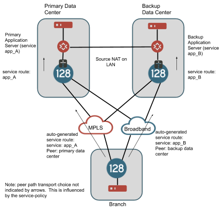
This is the most simple design when handling georedundant data centers as the application does most of the work. If there is a routable path between the data centers (e.g., on a dedicated link), the branch can be configured to allow failover of sessions for services between the primary and backup data center, by enabling peer-path-resiliency in the service-policy applied to each service. The negative to this is that in scenarios where client traffic from the branch is targeting address space in data center A and a catastrophic failure causes these sessions to migrate to the SSR in data center B, the NAT binding for the sessions will change. Some applications may handle this change in NAT smoothly, others may not. In our testing with UC applications, we have determined that typically it is better not to allow this router-to-router session failover and to let the application handle this type of failure by re-registering traffic to the other data center.
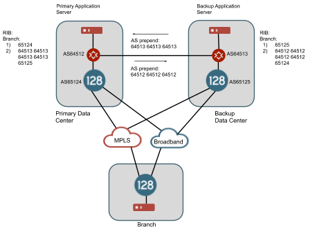
In other cases, the customer may have an existing mechanism to provide georedundancy between data centers through routing protocols. For example, the customer may use BGP to advertise their routes from each redundant data center. A private link between the data centers provides a path from one data center to the other and an AS prepend (as an example, other BGP mechanisms can be used to prefer routes) on these routes across the link will provide a mechanism to inform the branch routers of an alternate, but less preferred path, to this IP address space through the backup data center. BGP over SVR can provide a mechanism to share these routes learned from the SSRs in the head end to the branch routers even over public internet connections. An example of this architecture is shown below.
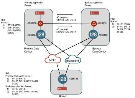
In this example, we assume that the router for AS65412 is announcing routes for the primary data center and the router for AS64513 is announcing routes for the backup data center. There is a path on a private link between these two data centers and the routers have a BGP neighbor relationship and a route filter on each one is prepending each one's AS three times in front of the AS path. The SSR in each data center has a BGP neighbor relationship with the local router in its data center. The SSR branch router with AS65535 is configured with a BGP over SVR peering relationship to both data center SSRs. It learns routes for the primary data center and the secondary data center from both BGP peers. However, the AS path is shorter for each route through the SSR locally within the data center so in a normal case, traffic will flow from the branch router over SVR to the SSR peer in the same data center as the IP space. If all peer paths to the SSR in the primary data center go down to the branch router, the BGP connection will time out and the routes through this router will be withdrawn from the RIB and now the only routes to the IP space in the primary data center will be through the SSR in the backup data center. Traffic will now flow from branch router over SVR to the SSR peer router in the backup data center. This traffic will leave the SSR as non-SVR traffic and flow up to the router at AS65413 and then across the private link to the router at AS64512 in order to reach this IP space. At the same time, since the peer paths from the SSR in the primary data center have gone down and the BGP connection to the branch router has expired, it will withdraw the route to the branch router from its neighbor at AS65412 and the best return path for this traffic will flow back across the intra data center link.
A variation of this failover model is also possible without using BGP over SVR. The SSR offers a configuration option called redistribute service in both OSPF and BGP configurations that allows the SSR to announce routes associated with a service when the service-route is up, and withdraw these routes when the service-route is down. This is illustrated in the drawing below.
In this drawing, a service exists covering the IP address space of the branch. A peer service-route exists on both the SSR in the primary and the backup data center and redistribute service is enabled in the BGP configuration of these routers. When the peer path connectivity is up between the data center and branch router, the routes are advertised to the BGP neighbor within the data center. If all peer paths to the branch go down, the route is withdrawn.
The service-policy for these services should have peer-path-resiliency set to true in order to allow sessions to fail over between the two data center routers.
Redistribute Service
In addition to standard redistribution statements like redistribute connected and redistribute static, the SSR has the option to redistribute service. When a service route is created for a service on a router, a kernel route is also created for each of the addresses in the service. When the SSR determines that the service-route is down, (e.g., a peer service-route, and the peer is unreachable) the kernel route is removed. When the service-route transitions back up, the kernel route is re-added. The redistribute service setting triggers the redistribution of these kernel routes into the routing protocol (OSPF or BGP). The SSR announces these routes when the service-route is up and withdraws the routes when the service-route is down. For added control, the redistribute service configuration also allows setting a policy to control which routes may be advertised.
In Mist deployments a specific combination of SSR and Mist configuration can result in a protocol redistribution scenario on the SSR for addresses configured for the application. In the case of the service any defined as 0.0.0.0/0, this can result in the SSR originating the default route. In scenarios where you are using BGP between the SSR and an existing network, this is likely undesirable. For more details about this interaction between redistribute service and Mist WAN Assurance, please refer to Mist Traffic Steering.
Neighborhood Design
Neighborhoods were mentioned briefly during the tenancy design portion of this document. However, their primary role of neighborhoods in most SSR networks is to assist with the automatic generation of adjacencies, which define how the routers establish their SSR peer paths between each other, and certain service-routes. A neighborhood in this sense is intended to conceptually define waypoints that are reachable between routers in an authority. If interfaces on two routers share a neighborhood, it is assumed that their waypoints are routable to each other (excepting the use case for tenancy mentioned in the other section of the document). For example, you would not share a neighborhood between interfaces that are connected to an MPLS network and those connected to broadband interfaces as those interfaces would never be able to establish a connection.
A waypoint can belong to multiple neighborhoods, and this allows us to specify different settings on different peer paths that use the same waypoint. For example, a deployment using LTE may want to use these paths only as a last resort. To reduce data usage and lower billing, the BFD timers on these paths may be raised so that peer path test traffic is sent less frequently. This can be accomplished by creating a neighborhood specific for LTE. In the data centers, likely the routers have an internet waypoint that is used for connections from branches both by broadband and by LTE. This waypoint would be a member of both a broadband neighborhood, with default BFD timers, and the LTE neighborhood with the dilated BFD timers. In the branches, the broadband interface would be a member of only the broadband neighborhood and the LTE interface would be a member of only the LTE neighborhood.
Your use of vectors and desired routing of applications between branch and data center may also dictate your neighborhood architecture. Neighborhoods can also contain vectors, which are then used in any underlying adjacencies created as a result of the neighborhood. A vector is merely a textual label used to describe a peer path. Common vectors would be "broadband", "lte", "mpls", "carrierA", "carrierB", etc. When you create services, you can configure a service-policy and these service-policies can have a list of the vectors which are allowed or forbidden for this traffic. The order of these vectors in the service-policy (or optionally a numerical priority configured by the user) will dictate the order of peer path preferences for this traffic. This is fairly straightforward when configuring traffic between branches and a single data center.
Site Design
This exercise should be completed for each site category.
High Availability Requirements
One of the most important considerations for any site is High Availability. High Availability provides business continuity in the event of a hardware failure as well as the ability to perform software upgrades and maintenance in a hitless manner in the site. However, this increases the cost of the project to the end customer and the complexity of the design, so there is a trade off. Consideration should be given for lead time to acquire new hardware in the site in the event of failure and whether this is acceptable for the customer, should a non-HA solution be selected.
Physical Interface Requirements
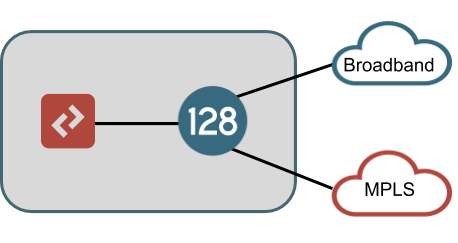
All, LAN, WAN, and HA connections should be enumerated here. A typical branch deployment will have one physical connection to each WAN's demarcation within the site and one or more LAN connections to the customer's L2 switch (or potentially an L3 device) as a demarcation within the site. A non-HA example of this is shown below, which would typically represent the most simple branch architecture for SD-WAN.
If HA is a requirement in the site, there are different architecture options to consider. In an HA configuration, one or more interfaces will be configured in a redundant manner allowing IP addresses of the router to float between nodes based on failure of interfaces or the nodes themselves. A router configured for full interface redundancy will look like the drawing below. This HA configuration is most commonly found in data center sites.
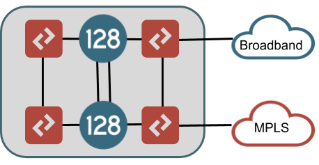
Both LAN and WAN connections are brought into L2 switch infrastructure which is then connected to both SSR nodes. The drawing shows different L2 switches at LAN and WAN sides of the topology, but these could in fact all be the same switches (using VLAN segmentation for each LAN and WAN network). It is recommended to use redundant switches with VLANs trunked between them to avoid a single point of failure.
An alternate HA configuration, which only provides interface redundancy for some connections, is shown in the drawing below. In this configuration, the LAN interfaces are redundant in exactly the same way as the fully interface redundant design above. However, the WAN connections are brought directly into a single node. This HA configuration is most common in branch sites. Reasons for this may be that the WAN connection does not offer redundancy (MPLS T1, LTE), or that the customer does not have L2 resources to use in front of the router, or that the customer desires to make the SSR LAN handoff their only demarcation point in the site.
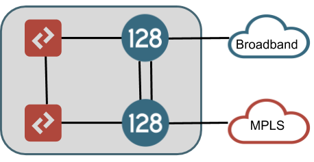
In this configuration, the different WAN connections should terminate to different nodes within the router so that a hardware failure of a node does not isolate the node's connectivity to the data centers it needs to communicate with. If local breakout nternet is required for access to any services that will not terminate across an SVR path to another SSR, special consideration should be given here as well because placing all internet reachable WAN connections on a single node would impact this service in the event of hardware failure in that node - unless there is a fallback path for this traffic over SVR through a data center on a private WAN connection.
In either HA configuration, one or more interfaces need to be allocated to providing connections between the SSR nodes. One interface per node at a minimum is required for HA synchronization which will allow the SSR software processes to communicate and share data. If a dedicated management interface is available for the router in this site, this can be used for HA sync although a dedicated direct cable is recommended as losing this communication due to switch failure would put the router into a bad operational state. Multiple connections can be grouped together in a teamed interface for this purpose to provide redundancy for this connection (for example to provide connection redundancy across multiple PCI cards in the same hardware).
Additionally, an interface may be desirable for customer traffic to traverse between the nodes within a site, this is called a fabric interface. Using a fabric interface allows traffic to ingress the router on the LAN of one node and egress the WAN of another node (or vice-versa). This should be considered a requirement when an HA design does not call for full WAN interface redundancy as lack of a fabric interface will lead to scenarios where traffic may become isolated. It may also be included for the fully redundant interface HA design where it is deemed desirable to have interfaces fail between nodes independently. However, in this architecture interfaces can be grouped into redundancy groups and all fail between nodes if any one experiences a failure, so it is not an absolute requirement.
In addition to LAN, WAN, HA sync, and fabric interfaces, additional consideration should be given for any dedicated management interfaces that should be incorporated into the design. Typically a branch router will not have a dedicated management interface and management connectivity will be handled through the dataplane using internal KNI devices. For data center deployments it is good practice to include a management interface to ensure an alternative mechanism for accessing the system outside of the dataplane. This interface should not share function with a LAN, WAN, or fabric interface as it should be a non SSR controlled interface. However, it may share function with the HA sync interface if this interface is connected through a switch which provides external access to the network.
For each site category, please add an entry for each physical interface connection. For HA routers indicate if this connection is on node A or B (for fully redundant interfaces be sure to include an entry for both nodes). Please indicate if the connection is WAN, LAN, HA sync, or fabric. Please describe the device it will connect to (customer L2 switch A, Broadband modem, or other SSR node are some examples). Please indicate the connection type required (ethernet, T1, or wireless). Add any additional comments necessary. For site categories that may have a variable number of connections (some sites with
| Site Category | Node (A or B) | LAN, WAN, HA sync, fabric, or mgmt | Connects To Device | Connection Type | Comments |
|---|---|---|---|---|---|
Hardware Selection
After determining the required number of connections, we can combine this data with the required max throughput to make a selection of the hardware required for each node at each site. In addition to ensuring the hardware provides a sufficient number of Ethernet ports, please also give thought to additional port requirements, such as a free PCI slot for supported T1 interfaces or usable USB ports for external LTE cards. It is recommended to use the same hardware for both nodes in an HA pair, but is not absolutely required should requirements dictate a need. Your SSR Sales Team can assist you in making this selection based on your requirements and our latest throughput testing. Please indicate the chosen hardware vendor and model in the last column.
| Site Category | Node (A or B) | Req'd Max throughput | Required Eth ports | Additional Req's | Selected Hardware |
|---|---|---|---|---|---|
Once hardware has been selected, please fill in the table below to map the physical interfaces to the hardware. The physical interface name is up to the network operator. Commonly the device interface name may refer to the physical port on the hardware for ease of communication with field services personnel. Another common convention is to name the device interface based on what it connects to or the role it performs (DIA, MPLS, WAN, LAN, FIREWALL, etc). Please indicate the device interface type in terms of the SSR data model (ethernet, t1, lte, host, bridged, etc). If the device is ethernet, be sure to include the PCI address mapping for the correct hardware. Lastly, in case the device interface name does not map to the physical port on the hardware, please be sure to include a "port identifier" to have some indication of which physical port this corresponds to. Ideally this value is the label for the interface visible on the hardware.
| Site Category | Node (A or B) | Device Interface name | Device Interface Type | PCI address | Port identifier |
|---|---|---|---|---|---|
Logical Topology
Each physical interface on the SSR will have one or more vlans. In the SSR data model, these map to the network-interface element configuration. WAN connections typically are not tagged and use vlan 0 whereas LAN connections may have multiple VLANs in order to provide Layer 2 segmentation of traffic. If this is not a greenfield deployment, the customer should have information on what VLANs exist at their sites and what the purpose of each VLAN is. If this is a greenfield deployment, you will have to work with the customer (particularly their security team) to decide on the appropriate VLAN configuration for their LAN in order to provide segmentation. Very simple deployments may also not be tagged and just provide a native vlan 0 on the LAN whereas very complicated deployments may have hundreds of VLANs.
Please use the chart below to enumerate each network-interface for each site category. If DHCP is to be used by the SSR to resolve its address, please indicate DHCP in the "IP addressing information" column. Often times, particularly in a retail store deployment, static IP addressing can be derived by some piece of information such as the store number. If a static IP address can be derived in such a manner, please indicate this information in the "IP addressing information" column. If static addressing is required and cannot be derived, this information will need to be determined before launch. The key item to think about at this point is deployment automation. Based on the size of the deployment and the speed of the desired rollout, will these sites need to be configured via template? If so, static IP (and subnet) information will need to be available in some database that can be queried in order to fill out the template.
Site Category Physical (device) Interface name Logical (network) Interface name Vlan Number IP addressing information