Step 4: Configure the Router on the Conductor
With the router VM initialized and connected to the conductor, you can now stage the full router configuration on the conductor. Once you commit the configuration, the conductor pushes it to the router and the router comes fully online.
All steps are performed from the Conductor GUI. Complete all steps before committing.
Your conductor must already have the following objects configured before proceeding:
- Authority name — set to your organization's name.
- Conductor address — set to
192.168.100.10. corptenant — the LAN-side user tenant.Internet-Trafficservice — with address0.0.0.0/0and access policy permittingcorp.
If any of these are missing, complete Configure the Conductor first.
Network Design Reference
The following IP addressing and naming scheme is used consistently throughout this guide. Substitute your own values when configuring your network.
| Parameter | Example Value | Description |
|---|---|---|
| Authority Name | Authority128 | Organizational authority name |
| Conductor Name | Conductor | Pre-existing conductor system name |
| Conductor IP Address | 192.168.100.10 | Conductor IP — must be reachable from the router WAN |
| Router Name | Spoke1 | VMware router system name |
| Router Node Name | node0 | Router node name |
| Router Asset ID | Spoke1 | Asset ID reported after initialization; see Step 2 |
| WAN Device Interface | wan-dev | WAN device interface name |
| WAN Network Interface | wan1 | WAN network interface name |
| WAN PCI Address | (discovered in Step 3) | VMXNet3 WAN NIC PCI address |
| LAN Device Interface | lan-dev | LAN device interface name |
| LAN Network Interface | lan1 | LAN network interface name |
| LAN PCI Address | (discovered in Step 3) | VMXNet3 LAN NIC PCI address |
| Router LAN IP Address | 192.168.1.1/24 | LAN gateway address |
| Tenant Name | corp | LAN-side user tenant |
| Service Name | Internet-Traffic | Internet breakout service |
| Service Address | 0.0.0.0/0 | All internet-bound traffic |
| Neighborhood | internet | SVR neighborhood name |
Complete the Router Configuration on the Conductor
During the Initialization process for your router, some basic information was provided, including router name (Spoke1), router location (Los Angeles), node name (node0), the inter-node security policy (internal), asset-id (Spoke1), and role (Combo). All of this allows the router to connect with the Conductor and onboard successfully.
This procedure configures network connections for the router.
If you prefer to use the CLI to perform configuration tasks, the example configuration is available in the Appendix.
-
Open a browser tab on your computer and navigate to your VMWare conductor;
https://192.168.100.10and initiate a web session to the conductor GUI.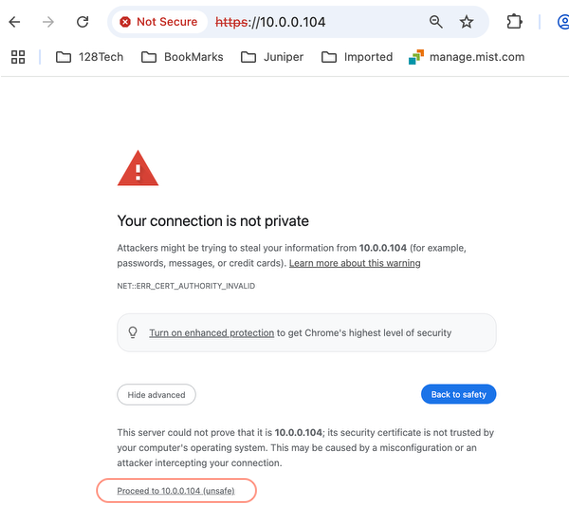
-
Accept the self-signed certificate warning, and login.
-
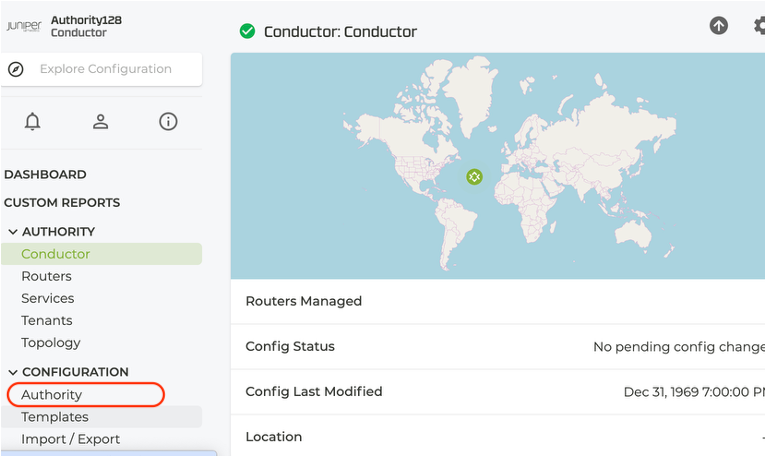
In the Conductor GUI, click on Authority.
-
Scroll to Routers and select the router
Spoke1. -
Scroll down to Nodes and select
node0.
1. Configure the WAN Interface
The WAN interface (NIC 1) connects to the ISP, obtains a DHCP address, and carries both internet forwarding and conductor management traffic via Management over Forwarding.
1a. Create the WAN Device Interface
-
Under the Node, scroll to Device Interfaces and select ADD.
-
Enter the name
wan-devand select SAVE.noteTo ensure successful onboarding, the
ge-0-0interface MUST be configured as the WAN device interface.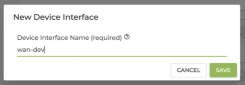
-
In the Device Interface window, set the following fields:
Field Value Notes Type ethernetPCI Address (WAN PCI address from Step 3) For example, 0000:0b:00.0Forwarding true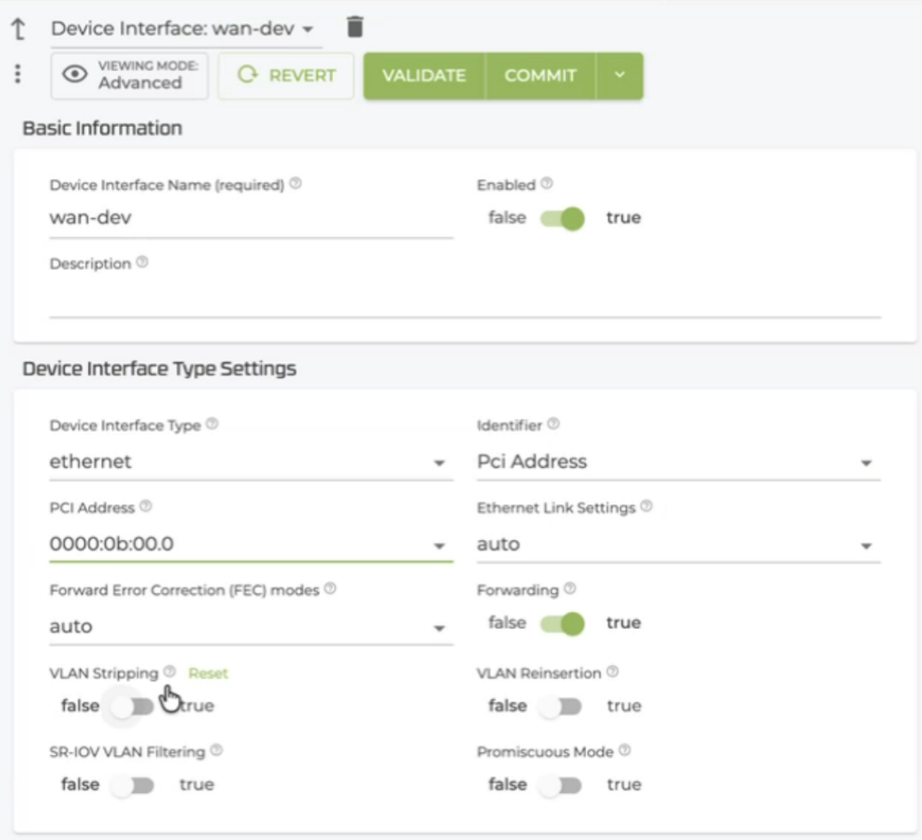
-
Select COMMIT.
1b. Create the WAN Network Interface
-
Under the WAN Device Interface, scroll to Network Interfaces and select ADD.
-
Enter the name
wan1and select SAVE.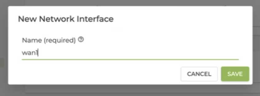
-
Set the following fields:
Field Value Notes Type externalDHCP disabledGlobal-ID 1Conductor trueMarks this interface for conductor connectivity Management trueEnables management over forwarding on this interface Default Route trueLinux uses this interface as its default route Source NAT trueRequired for management over forwarding 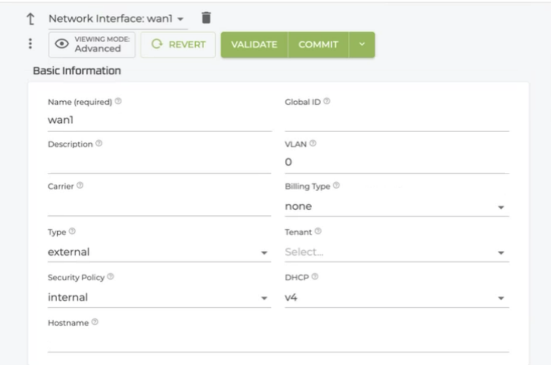
-
Scroll down to Management Traffic Settings.
- In the Management Vector Name, select
mgmt-vec-wanfrom the dropdown. - In the Management Vector Priority, enter
100. - Select COMMIT.
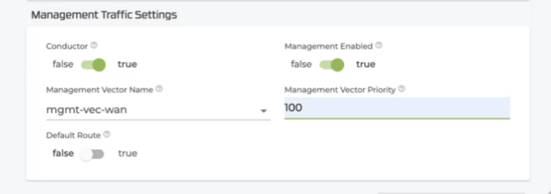
- In the Management Vector Name, select
-
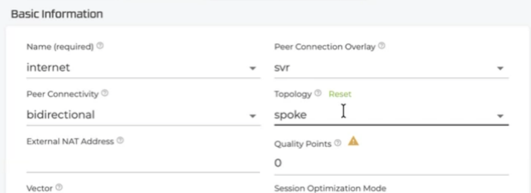
Scroll down to Neighborhoods and select ADD.
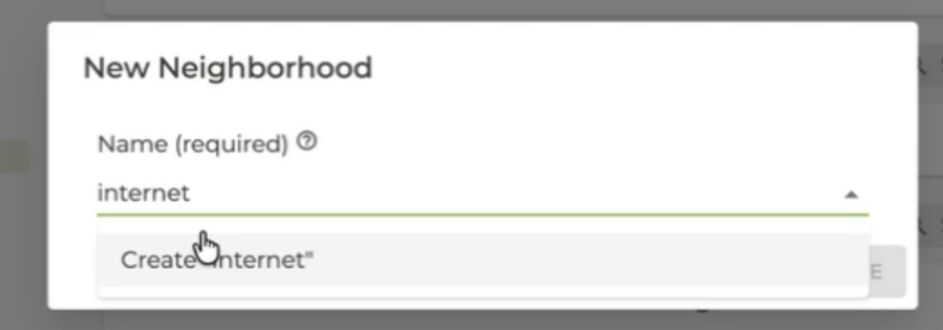
- Select
internetas the neighborhood name. - Verify Topology is set to
spoke.
- Select
-
Select SAVE.
Conductor must be set to true or management traffic will not be able to reach the conductor.
Source NAT and Default Route must both be set to true on the WAN management interface. Management traffic originates from the 169.254.x.x range and must be source-NAT'd to a routable address before leaving the interface. The default route ensures Linux routes non-SVR traffic through the SSR forwarding engine.
2. Configure the LAN Interface
The LAN interface (NIC 2) connects to the branch LAN and assigns the corp tenant to traffic arriving from that direction.
2a. Create the LAN Device Interface
-
From the Authority level in the Conductor GUI, click on
spoke1to begin configuration. -
Click on
node0and scroll to the bottom of the page. -
Select Device Interfaces, and ADD.
-
In the New Device Interface window, add the LAN device name
lan, and click SAVE. This adds a physical device name for you to assign your LAN interface.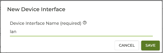
Set the following fields:
| Field | Value | Notes |
|---|---|---|
| Type | ethernet | |
| PCI Address | (LAN PCI address from Step 3) | For example, 0000:13:00.0 |
| Forwarding | true |
2b. Create the LAN Network Interface
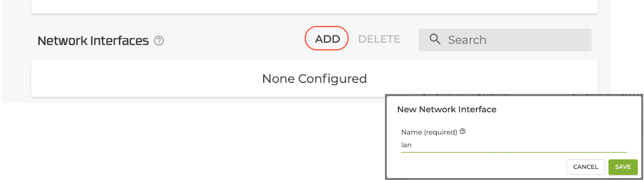
- Under the LAN Device Interface, scroll to Network Interfaces and select ADD.
-
Enter the name
lan1and select SAVE. -
Set the following fields:
Field Value Notes Type externalGlobal-ID 2DHCP disabledTenant corpAssigns all LAN traffic to the corp tenant Source-NAT true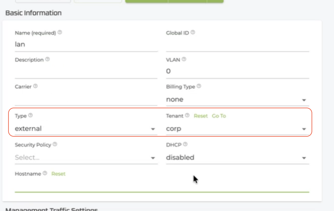
-
Scroll down to Interface Addresses and select ADD.
- IP Address:
192.168.1.1 - Prefix Length:
24
- IP Address:
-
Select SAVE.
3. Configure DNS
Configure DNS so the router can resolve FQDNs for conductor connectivity and software downloads.
-
Return to the Router level.
-
Scroll to DNS Config and select ADD.
-
Set Mode to
manualand enter DNS server addresses — for example,1.1.1.1and8.8.8.8. -
Select SAVE.

4. Create the Internet Service Route
The service route directs traffic matched by the Internet-Traffic service out through the WAN interface as a direct internet breakout.
-
Return to the Router level.
-
Scroll to Service Routes and select ADD.
-
Enter the name
internet-routeand select SAVE.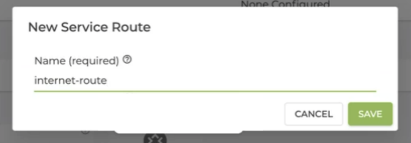
-
Set the following fields:
Field Value Service Name Internet-TrafficService Route Type service-agent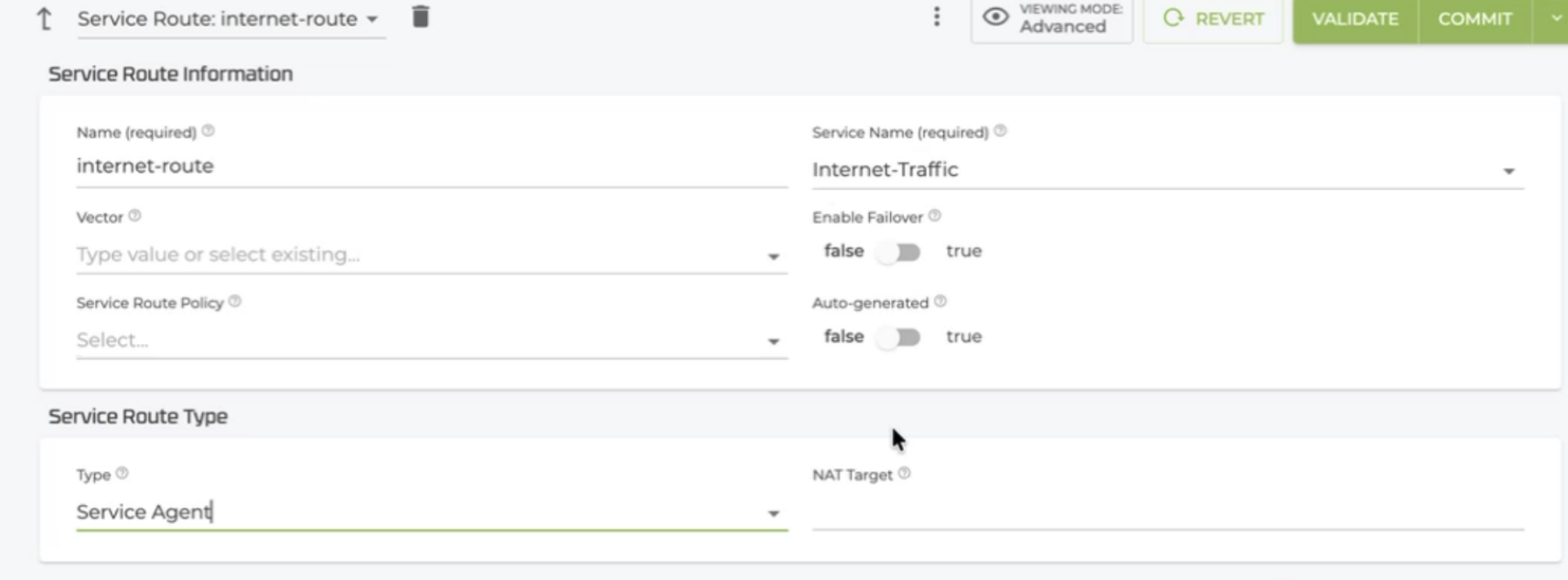
-
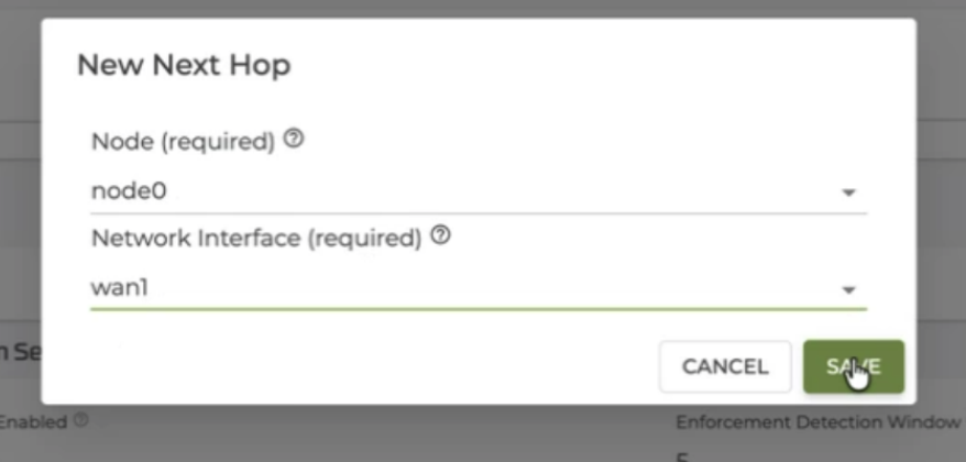
Scroll to Next Hop and select ADD.
- Node:
node0 - Network Interface:
wan1 - Select SAVE.
- Node:
-
Select VALIDATE and COMMIT.
Configuration Summary
After committing, the conductor pushes the following configuration to Spoke1. The router applies the configuration and comes fully online within approximately 2–5 minutes.
| Object | Name | Key Settings |
|---|---|---|
| Router | Spoke1 | combo node, asset-id Spoke1 |
| WAN Device Interface | wan-dev | VMware WAN NIC PCI address, forwarding enabled |
| WAN Network Interface | wan1 | DHCP, conductor, default-route, source-nat, management, neighborhood internet |
| LAN Device Interface | lan-dev | VMware LAN NIC PCI address, forwarding enabled |
| LAN Network Interface | lan1 | tenant corp, address 192.168.1.1/24 |
| DNS Config | manual | servers 1.1.1.1, 8.8.8.8 |
| Service Route | internet-route | service Internet-Traffic, type service-agent, next-hop node0/wan1 |
Next Step
Congratulations! At this point your router is ready for your testing and deployment!