Appendix: VMware Router Configuration
This appendix contains the complete SSR PCLI configuration for the Spoke1 VMware router described in this guide. This configuration reflects the final state after completing all steps through Step 4 — Configure the Router on the Conductor.
This appendix uses example PCI addresses (0000:0b:00.0 for WAN, 0000:13:00.0 for LAN). Replace these with the actual values discovered in Step 3 — Find VM NIC PCI Addresses.
Network Design Reference
The following IP addressing and naming scheme is used consistently throughout this guide. Substitute your own values when configuring your network.
| Parameter | Example Value | Description |
|---|---|---|
| Authority Name | Authority128 | Organizational authority name |
| Conductor Name | Conductor | Pre-existing conductor system name |
| Conductor IP Address | 192.168.100.10 | Conductor IP — must be reachable from the router WAN |
| Router Name | Spoke1 | VMware router system name |
| Router Node Name | node0 | Router node name |
| Router Asset ID | Spoke1 | Asset ID reported after initialization; see Step 2 |
| WAN Device Interface | wan-dev | WAN device interface name |
| WAN Network Interface | wan1 | WAN network interface name |
| WAN PCI Address | (discovered in Step 3) | VMXNet3 WAN NIC PCI address |
| LAN Device Interface | lan-dev | LAN device interface name |
| LAN Network Interface | lan1 | LAN network interface name |
| LAN PCI Address | (discovered in Step 3) | VMXNet3 LAN NIC PCI address |
| Router LAN IP Address | 192.168.1.1/24 | LAN gateway address |
| Tenant Name | corp | LAN-side user tenant |
| Service Name | Internet-Traffic | Internet breakout service |
| Service Address | 0.0.0.0/0 | All internet-bound traffic |
| Neighborhood | internet | SVR neighborhood name |
Applying This Configuration
This configuration can be applied to the conductor using the PCLI import function.
-
Save the router configuration block below to a file — for example,
vmware-router-Spoke1.cfg. -
Copy the file to the conductor:
scp vmware-router-Spoke1.cfg admin@192.168.100.10:/tmp/ -
Log in to the conductor PCLI:
ssh admin@192.168.100.10 -
Enter configuration mode and import:
admin@node0.conductor1# import config /tmp/vmware-router-Spoke1.cfg -
Review any validation warnings, then commit:
admin@node0.conductor1 (config)# commitAre you sure you want to commit the candidate config? [y/N]: y
Alternatively, copy and paste each block into the PCLI while in configure → edit mode.
The authority-level objects this router depends on (Internet-Traffic service, corp tenant, and conductor address) must already exist in the running configuration. For the complete authority-level configuration, see Appendix — VMWare Conductor Configuration.
Router Configuration
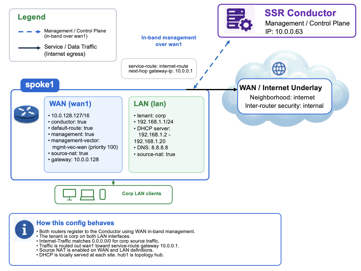
The following block shows the Spoke1 router configuration as it appears within the authority configuration.
config

    authority
        conductor-address  10.0.0.63


        router             Conductor
            name                  Conductor
            location-coordinates  +38.7127105-077.0060152/

            node                  node0
                name           node0
                asset-id       Conductor
                platform-type  "440BX Desktop Reference Platform"
            exit
        exit

        router             spoke1
            name                  spoke1
            location-coordinates  +34.7127281-118.0060152/
            inter-node-security   internal

            node                  node0
                name              node0
                asset-id          Spoke1
                role              combo
                platform-type     "440BX Desktop Reference Platform"

                device-interface  wan-dev
                    name               wan-dev
                    pci-address        0000:0b:00.0

                    network-interface  wan1
                        name                   wan1
                        global-id              1
                        conductor              true
                        default-route          true

                        neighborhood           internet
                            name  internet
                        exit
                        inter-router-security  internal
                        source-nat             true
                        management             true

                        management-vector
                            name      mgmt-vec-wan
                            priority  100
                        exit

                        address                10.0.128.127
                            ip-address     10.0.128.127
                            prefix-length  16
                            gateway        10.0.0.128

                            host-service   web
                                service-type  web
                            exit
                        exit
                        dhcp                   disabled
                    exit
                exit

                device-interface  lan
                    name               lan
                    pci-address        0000:13:00.0

                    network-interface  lan
                        name        lan
                        global-id   2
                        tenant      corp
                        source-nat  true

                        address     192.168.1.1
                            ip-address     192.168.1.1
                            prefix-length  24

                            host-service   dhcp-server
                                service-type  dhcp-server

                                address-pool  192.168.1.2
                                    start-address  192.168.1.2
                                    end-address    192.168.1.20
                                    router         192.168.1.1
                                    domain-server  8.8.8.8
                                exit
                            exit
                        exit
                        dhcp        disabled
                    exit
                exit
            exit

            service-route         internet-route
                name          internet-route
                service-name  Internet-Traffic

                next-hop      node0 wan1
                    node-name   node0
                    interface   wan1
                    gateway-ip  10.0.0.1
                exit
            exit
        exit

        tenant             corp
            name  corp
        exit

        software-access
            username  (removed)
            token     (removed)
        exit

        service            internet
            name      internet
            security  internal
        exit

        service            Internet-Traffic
            name           Internet-Traffic
            address        0.0.0.0/0

            access-policy  corp
                source  corp
            exit
        exit
    exit
exit
Interface Summary
| Interface | Device Interface | PCI Address | Type | Configuration |
|---|---|---|---|---|
wan1 | wan-dev | 0000:0b:00.0 (example) | External | DHCP, conductor, default-route, source-nat, management, neighborhood internet |
lan1 | lan-dev | 0000:13:00.0 (example) | External | tenant corp, static 192.168.1.1/24 |
Service Route Summary
| Service Route | Service | Type | Next Hop |
|---|---|---|---|
internet-route | Internet-Traffic | service-agent | node0 / wan1 |
Design Notes
Management over Forwarding — The wan1 interface carries both internet traffic and conductor management sessions simultaneously. Management traffic from the 169.254.x.x range is source-NAT'd to the WAN DHCP address before leaving the interface. This eliminates the need for a separate out-of-band management network at the branch site.
Internet Breakout — The internet-route service route directs all corp-tenant traffic matching the Internet-Traffic service (destination 0.0.0.0/0) out through wan1 as a service-agent. The source NAT setting on wan1 ensures LAN client traffic is translated to the WAN IP before it reaches the ISP.
PCI Address Binding — VMware assigns PCI addresses based on the VM's hardware slot configuration. The example addresses in this appendix (0000:0b:00.0, 0000:13:00.0) are illustrative only. Always use the values discovered by following Step 3 — Find VM NIC PCI Addresses.