Cloud High Availability Plugin
The SSR-cloud-ha plugin provides High Availability (HA) functionality for the SSR Networking Platform deployed in the cloud. HA for SSR routers in a non-cloud environment uses traditional techniques such as VRRP and GARP which both rely on a virtual MAC and virtual IP. In cloud environments such as AWS, Azure, etc., any techniques that rely on broadcast and multicast are not supported. This plugin uses node health metrics sent over SVR, as well as cloud API interactions to perform failovers in these cloud environments.
For instructions to install and manage the plugin, see Installation and Management.
Supported Modes
Across supported versions, the Cloud HA plugin supports two modes of operation: dual-node and dual-router.
Cloud HA Plugin 6.08 was released on July 1, 2026 to provide support for node-based HA (Dual-Node mode). Cloud HA plugin 6.0 does not support dual-router mode.
Dual Node Mode
In dual-node mode, two nodes belong to the same router. This mode is suitable for scenarios where redundancy is required within a single router. Both nodes share the same configuration and operate in a coordinated manner to ensure high availability. The failover process is managed internally within the router, leveraging the health status of the nodes to determine which node should be active.
Dual Router Mode (Legacy, Versions Earlier Than 6.x)
In dual-router mode, two routers are configured, each with one node. This mode is designed for scenarios where redundancy is required across separate routers. Each router operates independently, and the Cloud HA plugin ensures that only one node is active at a time. The failover process involves communication between the routers to determine the health and status of the nodes, ensuring seamless traffic handling during failover events.
These modes provide flexibility in deploying high availability solutions based on the specific requirements of the network architecture.
Version 6.x supports dual-node mode only; dual-router mode is not supported. On versions earlier than 6.x, dual-node mode is not supported.
Dual-node supported solutions are azure-vnet, aws-vpc, aws-tgw, and gcp-vpc.
Supported Solutions
| Solution Name | solution-type | Available In Version |
|---|---|---|
| Azure VNET | azure-vnet | 2.0.0 |
| Azure Loadbalancer | azure-lb | 2.0.0 |
| Alicloud VPC | alicloud-vpc | 3.0.0 |
| AWS VPC | aws-vpc | 6.0.0 |
| AWS TGW | aws-tgw | 6.0.0 |
| GCP VPC | gcp-vpc | 6.0.0 |
Version Restrictions
The router component can only be installed on versions of SSR which support provisional state on device interfaces. This is necessary for the plugin to be able to prevent asymmetrical routing.
The versions of SSR that support this feature have a Provides: 128T-device-interface-api(1.0), so it can be checked ahead of time by performing a rpm -q --whatprovides 128T-device-interface-api(1.0) to see if the currently installed 128T satisfies this requirement or dnf list --whatprovides 128T-device-interface-api(1.0) to see all versions of SSR that satisfy this requirement.
Plugin Behavior
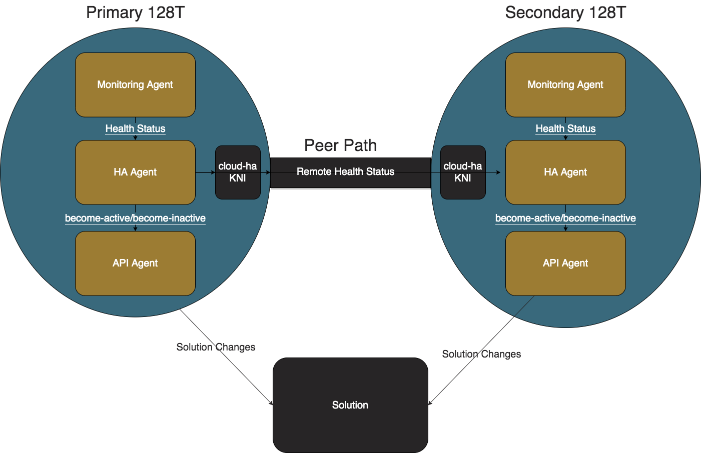
Monitoring Agent
The job of the Monitoring Agent is to produce and transmit health status messages. The Monitoring Agent collects the administrative status, operational status, and mac address of all of the configured redundant interfaces and additional interfaces at one second intervals. The health status is then sent via an HTTP POST to the IP address of the cloud-ha interface where the HA Agent is listening on port 12800.
HA Agent
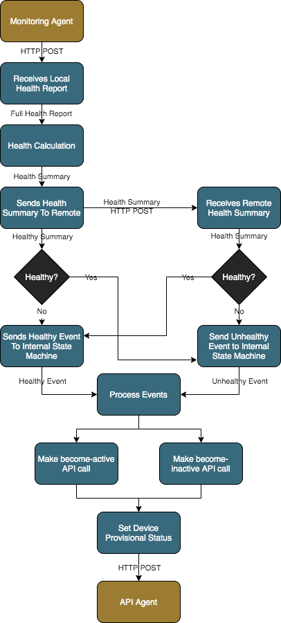
The job of the HA Agent is to process the health status messages from the the local Monitoring Agent and determine the health status for performing failover operations. For an interface to be healthy, it must be administratively and operationally up. For a node to be healthy, it must have at least one healthy redundant-interface. If there are additional interfaces configured, then the node must have at least one healthy additional-interface.
The following flow diagram summarizes the process followed by the HA Agent using information supplied by the Monitoring Agent, and resulting in interactions with the API Agent.
An HA Agent configured with a priority of 1 will be defined as the Primary node; a priority of 2 becomes the Secondary node.
- Primary: This node is preferred to be active except when the local node is unhealthy.
- Secondary: This node is preferred to become active only when the local node is healthy and the remote node is unhealthy or unreachable.
The internal state machines wait for the value set in seconds in up-holddown-timeout before considering a node healthy. If at any point during that wait the HA Agent receives an unhealthy status, the timeout will be reset and the node is considered unhealthy.
The internal state machines wait for the peer-reachability-timeout after every health status before considering the node unreachable. The timer is reset if a health report is processed before the timeout expires.
When the HA Agent determines that a node must become active, the first active redundant interface's MAC address and the list of configured prefixes are sent to the API Agent's appropriate REST endpoint. The HA Agent changes the provisional status of the configured redundant-interface to Up.
API Agents
The job of the API Agent is to perform failover actions specific to the cloud provider and the chosen solution.
Azure Loadbalancer
A solution-type of azure-lb can be used to enable the Azure Loadbalancer API agent. This solution requires an Azure Loadbalancer to be configured using an HTTP probe on the probe-port with backend pools pointing towards the redundant interfaces.
Probe example:

Backend Pool example:

The Azure Loadbalancer sends a health probe to the redundant SSR's redundant interfaces. These probes are routed through the cloud-ha interface, through a 128T-azure-lb-nginx instance, and down to the Azure Loadbalancer API Agent.
The Azure Loadbalancer API Agent responds to the probes with a 200 status code when the current node is active and a 500 code when its inactive. A probe to the inactive node will not reach the SSR when the redundant interfaces are set provisionally down.
Azure VNET
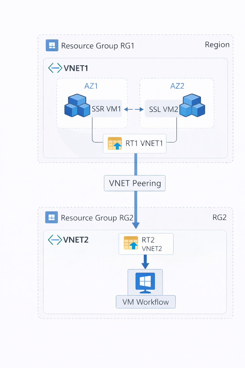
A solution-type of azure-vnet can be used to enable the Azure VNET API agent. It requires an Azure Route Table setup on the same VNET as the redundant interfaces. The Virtual Machines where these members are running must be granted the following permissions in order for the route updates to work correctly:
- Microsoft.Network/routeTables/read
- Microsoft.Network/networkInterfaces/read
- Microsoft.Network/routeTables/routes/*/write
- Microsoft.Network/routeTables/routes/read
- Microsoft.Compute/virtualMachines/read
- Microsoft.Network/virtualNetworks/read
The agent finds all of the route tables within the VNET using the Azure REST APIs. When a redundant interface becomes active, the agent updates the route tables for all the configured prefixes to point to that interface. The solution is designed to be idempotent, so the peer member's redundant interface will now be inactive. There is no update to the route table needed when becoming inactive.
Microsoft.Network/virtualNetworks/read is only necessary when the plugin should discover and modify peer VNET route tables. This feature can be enabled by configuring include-peer-vnets to true.
To prevent routing loops, the solution will not update the Azure Route Tables assigned to a subnet that has an activating node's network interface.
Extra Route Tables
By default, the Azure VNET solution automatically discovers all route tables within the VNET where the redundant interfaces are located. However, you can also explicitly specify additional Azure Route Tables (User Defined Routes or UDRs) to be managed by the plugin using the extra-route-table configuration.
Each extra-route-table entry requires:
subscription-id: The unique identifier of the Azure subscription containing the UDRresource-group: The name of the Azure resource group where the route table is hostedroute-table-name: The specific name of the Azure Route Table resource
This is particularly useful when you need to manage route tables in different subscriptions or resource groups that are not automatically discovered.
Route Table Discovery
The auto-discover-route-table setting (default: true) enables automatic discovery of Azure Route Tables within the specified VNET. When enabled, the system first scans for tags (see Tagging below). If none are found, then the system scans for existing UDRs instead of requiring manual entry via extra-route-table. Setting this to false means only explicitly configured extra-route-table entries are managed.
Tagging
When auto-discover-route-table is set to true in the cloud-redundancy-group, the API Agent looks for the Route Table by looking at the tags assigned to the VM.
To utilize this feature, the tags must follow the following form:
SSR-CLOUD-HA-<TAG_IDX>-SUBSCRIPTION-ID:<subscription-id>SSR-CLOUD-HA-<TAG_IDX>-RESOURCE-GROUP:<resource-group-name>SSR-CLOUD-HA-<TAG_IDX>-ROUTE-TABLE-NAME:<route-table-name>
The Subscription ID, Resource Group, and Route Table Name must be the same for both nodes in a redundancy group.
The following are some example tags:
SSR-CLOUD-HA-0-SUBSCRIPTION-ID:88888888-bbbb-4444-aaaa-ffffffffffffSSR-CLOUD-HA-0-RESOURCE-GROUP:myResourceGroupSSR-CLOUD-HA-0-ROUTE-TABLE-NAME:myRouteTable
When auto-discover-route-table is true and the tags are missing or incomplete, the API Agent uses the existing UDRs.
These tags are queried each time the API Agent tries to get state or become-active, so modifying these tags during runtime is allowed.
AWS TGW
A solution-type of aws-tgw can be used to enable the AWS TGW API agent. This solution requires a TGW to be created with attachments which are connected to the VPCs that the SSR resides in. The Virtual Machines where these members are running must be granted the following permissions in order for the route updates to work correctly:
- ec2:DescribeInstances
- ec2:CreateTransitGatewayRoute
- ec2:DescribeTransitGatewayRouteTables
- ec2:ReplaceTransitGatewayRoute
If you want the state output to report the current routes in the TGW Route Rable, the VMs will also need:
- ec2:SearchTransitGatewayRoutes
The AWS metadata configuration for the SSR instances must set the Hop Limit to a minimum of two (2) for the plugin to make the correct API calls. This is the default setting in the BYOL AMI, however that value is only used if the instance or account settings are not specified.
The TGW Route Table is updated by the plugin, pointing to one of the node's TGW Attachments. Each SSR node must know the TGW Route Table as well as the corresponding attachment that points to itself. This configuration is explained in AWS TGW Configuration
Tagging
When auto-discover-route-table is set to true in the cloud-redundancy-group, the API Agent looks for the TGW Route Table and Attachment by looking at the tags assigned to the EC2 instance.
To utilize this feature, the tags must follow the following form:
SSR-CLOUD-HA-<TAG_IDX>-TGW-ROUTE-TABLE-ID:<tgw-rtb-id>SSR-CLOUD-HA-<TAG_IDX>-TGW-ATTACHMENT-ID:<tgw-attach-id>
The Route Table ID must be the same for both nodes in a redundancy group. The Attachment ID must be unique across nodes in a redundancy group.
The following are some example tags:
SSR-CLOUD-HA-0-TGW-ROUTE-TABLE-ID:tgw-rtb-000000000000SSR-CLOUD-HA-0-TGW-ATTACHMENT-ID:tgw-attach-000000000000
When auto-discover-route-table is true and the tags are missing or incomplete, the API Agent does not function. Any errors can be found in the journal.
These tags are queried each time the API Agent tries to get state or become-active, so modifying these tags during runtime is allowed.
GCP VPC
A solution-type of gcp-vpc can be used to enable the GCP VPC API agent. This solution requires an instance to be created with VPCs which are peered to the VPCs where the SSR resides. The Virtual Machines where these members are running must be granted the following permissions for the route updates to work correctly:
- compute.routes.list
- compute.routes.get
- compute.routes.create
- compute.routes.delete
- compute.instances.get
The VPC's Route Table is the object updated by the plugin. Each SSR node must be configured to manage routes on a VPC. This configuration process is explained in GCP VPC Tagging
Tagging
When auto-discover-route-table is set to true in the cloud-redundancy-group, the API Agent looks for the VPC Route Table by looking at the tags assigned to the instance.
To utilize this feature, the tags must follow the following form:
ssr-cloud-ha-<TAG_IDX>-target-vpc:<gcp-vpc-name>
The VPC Name must be the same for both nodes in a redundancy group.
The following is an example tag:
ssr-cloud-ha-0-target-vpc:ssr-private
When auto-discover-route-table is true and the tags are missing or incomplete, the API Agent will update the VPC route table associated with the redundant-interface configured in the cloud-redundancy-membership.
These tags are queried each time the API Agent tries to get state or become-active, so modifying these tags during runtime is allowed.
Scenarios
Both Healthy
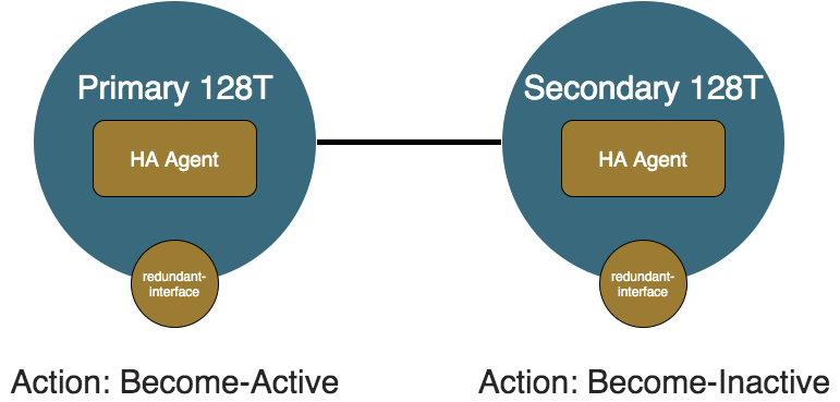
In the case where both members are healthy, the primary node is preferred and set to active. The secondary node is inactive. The redundant interface on the secondary node is set provisionally down and the API Agent steers traffic towards the primary node.
Primary Failure
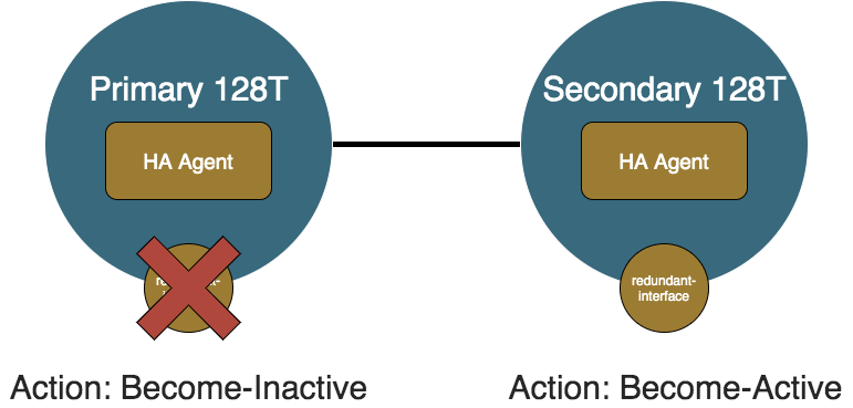
When the primary node becomes unhealthy and the redundant interfaces are operationally down, the Monitoring Agent sends an unhealthy status to the local HA Agent. When the local node is deemed unhealthy, the local HA Agent sends an unhealthy message to the remote HA Agent, and notifies the internal state machine. When the primary node recognizes it is no longer fit to process traffic, it becomes inactive. The secondary node recognizes the primary node is not processing traffic, and the secondary node is healthy so the secondary node becomes active.
Primary Recovery
Now something causes the primary node to recover and the redundant-interface becomes healthy again. The healthy statuses will propagate to the primary and secondary HA Agents and they will update their internal state machines which will determine that they are back to the Both Healthy Scenario. The primary node will become active and the secondary node will become inactive.
Secondary Failure
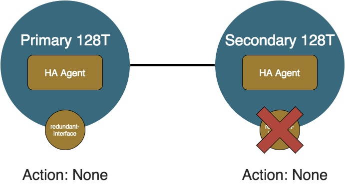
Now let us consider after recovering, the secondary node becomes unhealthy. The primary node will recognize that it is still healthy so it will not do anything and continue to process traffic. The secondary node will also realize that it is unfit to process traffic so it will also not do anything and continue sit idle.
Secondary Recovery
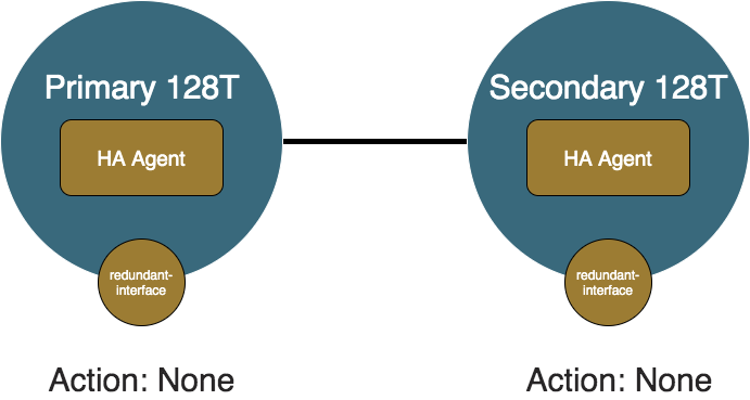
If the problem with the secondary node resolves, then the HA Agents will update their internal state, but again since traffic is preferred to flow the same as before, both the primary and secondary will not perform any API calls to the API Agents.
Primary Shutdown
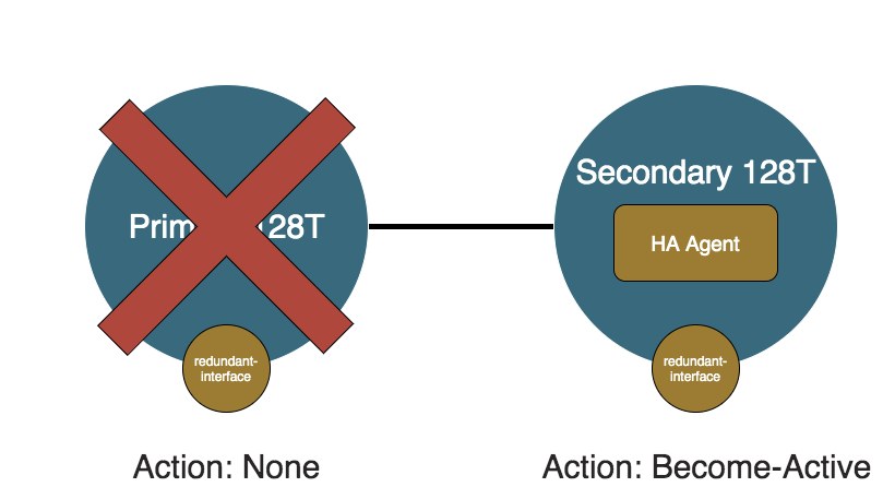
This scenario is what will occur if the primary node were to be taken down for maintenance or failed completely. The primary node's HA Agent (and Monitoring Agent and API Agent) will be shutdown when SSR is shutdown, so it will not perform any failover operations. The secondary node will wait for peer-reachability-timeout seconds of not hearing from the primary node to determine that the secondary node is unreachable. Once the primary node is determined unreachable, the secondary HA Agent will take over and become active since it does not know if the primary node is shutdown or unreachable.
Secondary Shutdown
If the secondary node is shutdown while the primary is healthy, the primary HA Agent will determine the secondary node unreachable. Similar to the the Secondary Failure scenario, since the primary node is preferred, it will not do anything and continue to process traffic.
Split Brain
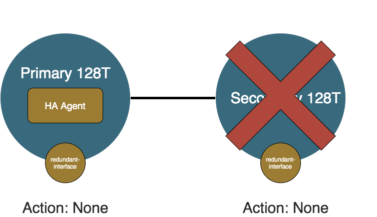
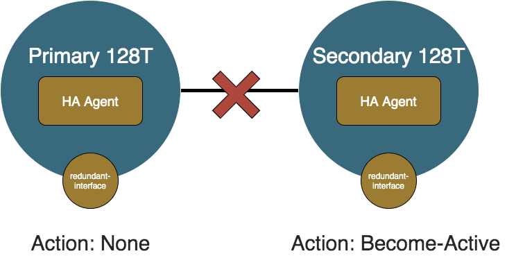
Split Brain is distinct from the Primary Shutdown or Secondary Shutdown because both nodes and HA Agents are up and running, but the peer link between the nodes is down. In this case, both HA Agents determine that the other HA Agent is unreachable. Because each node cannot distinguish this from the other node being shut down, both HA Agents determine they are in the position to take control of traffic. The node that was inactive becomes active, resulting in both nodes having their redundant-interfaces provisionally up. For the azure-vnet solution, there is still only be one node where the route tables are pointing. For the azure-lb solution, both nodes respond to the probes, causing traffic to split along the Azure Loadbalancer configuration. The result is asymmetrical routing; branch traffic comes in on the node that the solution is not pointed towards, is sent into Azure through that node, and then comes back in through the other node.
The split brain scenario can be identified when the peers cannot reach each other. This is captured with following alarms:
# show alarms

========================= ===================== ========== ======== =========== =======================================
 ID                        Time                  Severity   Source   Category    Message
========================= ===================== ========== ======== =========== =======================================
 router.node:11            2020-12-16 05:40:40   CRITICAL   router2    PEER      Peer router2 is not reachable
 router2.node2:10          2020-12-16 05:40:42   CRITICAL   router     PEER      Peer router is not reachable
Another indicator of a split brain scenario is having the remote-status be unreachable for the state output for both members.
Split Brain Resolution
Once the health status is able to flow between the two nodes, the unreachable status that each Cloud HA Agent has for the other node will resolve to healthy or unhealthy. Even if the determination of whether the node is the same as it was before, each HA Agent still sets the provisional statuses and makes the appropriate HTTP call on API Agent. This is because each node does not know what calls the other node made while the split brain was occurring, so it is safer to make calls even if it may not be necessary. Consider the scenario where the primary node is active and the secondary node is inactive before a split brain. When the split brain occurs, the secondary will then become active. If this is with a solution like azure-vnet, the last node to hit the API Agent will be the one that the solution point to. Thus the secondary node will be the active node from the Azure Route Table's perspective. Once the split brain is resolved, without the extra API calls, the primary would stay active without making any API calls and the secondary would become inactive. The problem with this is that the last node to trigger the API Agent was the secondary node so all branch bound traffic would be sent into interfaces that are provisionally down. The plugin solves this by reperforming API calls when it detects that the remote node goes from unreachable to not unreachable.
Configuration
Groups
A group is a collection of nodes which all share the same settings such as the solution type. In the below configuration snippet, there is an example of each of the supported solution types with the solution-specific configuration explicitly configured with their defaults. group1 has all of the solution-agnostic configuration settings explicitly configured with their defaults.
authority
    cloud-redundancy-group group1
        name group1
        enabled true
        solution-type azure-lb
        additional-branch-prefix 1.1.1.1/32
        additional-branch-prefix 2.2.2.2/24
        up-holddown-timeout 2
        peer-reachability-timeout 10
        health-interval 2
    exit
    cloud-redundancy-group group2
        name group2
        solution-type azure-vnet
        extra-route-table a1b2c3d4-e5f6-4789-a0b1-c2d3e4f5a6b7
            subscription-id a1b2c3d4-e5f6-4789-a0b1-c2d3e4f5a6b7
            resource-group azure-resource-group
            route-table-name azure-route-table
        exit
        auto-discover-route-table false
        include-peer-vnets false
    exit
    cloud-redundancy-group group3
        name group3
        enabled true
        solution-type aws-tgw
        auto-discover-route-table true
        health-interval 2
    exit
exit
Common Configuration
| Element | Type | Properties | Description |
|---|---|---|---|
| name | string | key | The name of the group to be referenced. |
| enabled | boolean | default: true | Whether the group is enabled. |
| solution-type | enum | required | The solution to use on member nodes. Value can be one of the values in Supported Solutions. |
| additional-branch-prefix | list: ip-prefix | Additional IP prefixes that the member routers will control. | |
| up-holddown-timeout | int | default: 2 | The number of seconds to wait before declaring a member up. |
| peer-reachability-timeout | int | default: 10 | The number of seconds to wait before declaring a peer unreachable. This field must be at least twice the value of health-interval. |
| health-interval | int | default: 2 | The interval in seconds for health reports to be collected. |
| remote-health-network | ip-prefix | default: 169.254.180.0/24 | The ip-prefix to use for inter-member health status messages. |
Azure VNET Specific Configuration
| Element | Type | Properties | Description |
|---|---|---|---|
| include-peer-vnets | boolean | default: false | Whether to include peer VNETs as part of the route table discovery algorithm. |
| auto-discover-route-table | boolean | default: true | Enables automatic discovery of Azure Route Tables within the specified VNET. |
| extra-route-table | list | A list of Azure User Defined Route (UDR) tables where custom routing entries will be injected or modified. | |
| subscription-id | string | key (within extra-route-table) | The unique identifier of the Azure subscription containing the UDR. |
| resource-group | string | required (within extra-route-table) | The name of the Azure resource group where the route table is hosted. |
| route-table-name | string | required (within extra-route-table) | The specific name of the Azure Route Table resource. |
Azure Loadbalancer Specific Configuration
| Element | Type | Properties | Description |
|---|---|---|---|
| probe-port | port | default: 12801 | The port where the Azure Loadbalancer sends HTTP probes. |
AWS TGW Specific Configuration
| Element | Type | Properties | Description |
|---|---|---|---|
| tgw-route-table-id | AWS ID | The TGW Route Table ID that should be updated. Ex. tgw-rtb-00000000000000001. Must be paired with the tgw-attachment-id on each member. |
Membership
Membership is how a node declares that it is part of a group. The configuration for a membership exists under the node and is where the node-specific configuration exists.
node
    cloud-redundancy-plugin-network 169.254.137.0/30

    cloud-redundancy-membership group1
        cloud-redundancy-group group1
        priority 1
        redundant-interface private
        redundant-interface private2
        additional-interface public1
        additional-interface public2
        log-level
            ha-agent info
            api-agent info
        exit
    exit
exit

...

node
    cloud-redundancy-membership group1
        cloud-redundancy-group group1
        priority 2
        redundant-interface private
    exit
exit
| Element | Type | Properties | Description |
|---|---|---|---|
| cloud-redundancy-plugin-network | ip-network | default: 169.254.137.0/30 | The ip network to use for internal networking. This should only be configured when the default value conflicts with a different service in the configuration. |
| cloud-redundancy-group | reference | required | The group that this member belongs to. |
| enabled | bool | default: true | Whether to enable the HA Agent from becoming active/inactive for the member. |
| dns-server | list: ipv4 | max-value: 2 | DNS servers to be used for Cloud HA management traffic. If omitted, solution-specific defaults are used. |
| tgw-attachment-id | string | The TGW Attachment ID to use when this member becomes active (for aws-tgw). If this is omitted, use tags for discovery. | |
| priority | int | min-value: 1, max-value:2 | The priority of the member where lower priority has higher preference. |
| redundant-interface | list: reference | min-number: 1 | The device interfaces that will be redundant with the redundant-interfaces on the peer members. |
| additional-interface | list: reference | The device interfaces that will be considered for node health, but not considered for redundant operations. | |
| log-level/ha-agent | log-level | default: info | The log level for the HA Agent. |
| log-level/api-agent | log-level | default: info | The log level for the active API Agent. |
Nodes can only be members of one group.
AWS TGW Specific Configuration
| Element | Type | Properties | Description |
|---|---|---|---|
| tgw-attachment-id | AWS ID | The TGW Attachment ID that should be used for this node when updating the route table entry. Ex. tgw-attach-00000000000000001 |
Address Prefixes
Certain prefixes can be configured to be controlled by the Cloud HA SSR by tagging services with groups. The services that are tagged with a certain group will have all of their address fields added to the list of configured prefixes.
service
    address 3.3.3.3
    address 4.4.4.4/24
    cloud-redundancy-group group1
    cloud-redundancy-group azure-vnet
exit
Any additional prefixes that should be included in the controlled prefix list can be configured as additional-branch-prefixs under the group.
Complete Azure VNET Configuration Example
Below is a complete working example of an Azure VNET High Availability deployment. This configuration demonstrates the use of explicit route table configuration using extra-route-table with auto-discover-route-table set to false.
This example is based on a production deployment pattern. Adjust the IP addresses, subscription IDs, and resource identifiers for your specific environment.
config
    authority
        cloud-redundancy-group  group1
            enabled                    true
            name                       group1
            solution-type              azure-vnet

            extra-route-table          a1b2c3d4-e5f6-4789-a0b1-c2d3e4f5a6b7
                subscription-id   a1b2c3d4-e5f6-4789-a0b1-c2d3e4f5a6b7
                resource-group    azure-resource-group
                route-table-name  azure-route-table
            exit
            auto-discover-route-table  false
            health-interval            6
            additional-branch-prefix   1.1.1.1/32
            up-holddown-timeout        2
            peer-reachability-timeout  13
        exit

        router                  azure-ha
            name                 azure-ha
            inter-node-security  internal

            node                 node0
                name                         node0
                asset-id                     node0-asset-id
                role                         combo

                device-interface             ge-0-1
                    name               ge-0-1
                    enabled            true

                    network-interface  ge-0-1-intf
                        name        ge-0-1-intf
                        tenant      lan
                        source-nat  true

                        address     172.16.10.4
                            ip-address     172.16.10.4
                            prefix-length  24
                            gateway        172.16.10.1
                        exit
                    exit
                exit

                device-interface             ge-0-2
                    name               ge-0-2
                    forwarding         false

                    network-interface  ge-0-2-intf
                        name       ge-0-2-intf
                        type       fabric

                        address    192.168.10.132
                            ip-address     192.168.10.132
                            prefix-length  29
                            gateway        192.168.10.129
                        exit
                    exit
                exit

                cloud-redundancy-membership  group1
                    cloud-redundancy-group  group1
                    dns-server              168.63.129.16
                    priority                1
                    redundant-interface     ge-0-1
                exit
            exit

            node                 node1
                name                         node1
                asset-id                     node1-asset-id
                role                         combo

                device-interface             ge-0-1
                    name               ge-0-1
                    enabled            true

                    network-interface  ge-0-1-intf
                        name        ge-0-1-intf
                        tenant      lan
                        source-nat  true

                        address     172.16.10.6
                            ip-address     172.16.10.6
                            prefix-length  24
                            gateway        172.16.10.1
                        exit
                    exit
                exit

                device-interface             ge-0-2
                    name               ge-0-2
                    forwarding         false

                    network-interface  ge-0-2-intf
                        name       ge-0-2-intf
                        type       fabric

                        address    192.168.10.134
                            ip-address     192.168.10.134
                            prefix-length  29
                            gateway        192.168.10.129
                        exit
                    exit
                exit

                cloud-redundancy-membership  group1
                    cloud-redundancy-group  group1
                    dns-server              168.63.129.16
                    priority                2
                    redundant-interface     ge-0-1
                exit
            exit

            service-route        internet-from-lan-route
                name             internet-from-lan-route
                service-name     internet-from-lan
                enable-failover  true

                next-hop         node1 ge-0-0-intf
                    node-name  node1
                    interface  ge-0-0-intf
                exit

                next-hop         node0 ge-0-0-intf
                    node-name  node0
                    interface  ge-0-0-intf
                exit
            exit
        exit

        tenant                  lan
            name  lan
        exit

        service                 internet-from-lan
            name     internet-from-lan
            enabled  true
            tenant   lan
            address  0.0.0.0/0
        exit
    exit
exit
Complete AWS TGW Configuration Example
Below is a complete working example of an AWS TGW High Availability deployment. This configuration demonstrates the use of explicit route table configuration using tgw-route-table-id and tgw-attachment-id.
This example is based on a production deployment pattern. Adjust the IP addresses, subscription IDs, and resource identifiers for your specific environment.
config
    authority
        cloud-redundancy-group  group1
            enabled                    true
            name                       group1
            solution-type              aws-tgw

            tgw-route-table-id         tgw-rtb-00000000000000001
            health-interval            6
            additional-branch-prefix   1.1.1.1/32
            up-holddown-timeout        2
            peer-reachability-timeout  13
        exit

        router                  aws-ha
            name                 aws-ha
            inter-node-security  internal

            node                 node0
                name                         node0
                asset-id                     node0-asset-id
                role                         combo

                device-interface             ge-0-1
                    name               ge-0-1
                    enabled            true

                    network-interface  ge-0-1-intf
                        name        ge-0-1-intf
                        tenant      lan
                        source-nat  true

                        address     172.16.10.4
                            ip-address     172.16.10.4
                            prefix-length  24
                            gateway        172.16.10.1
                        exit
                    exit
                exit

                device-interface             ge-0-2
                    name               ge-0-2
                    forwarding         false

                    network-interface  ge-0-2-intf
                        name       ge-0-2-intf
                        type       fabric

                        address    192.168.10.132
                            ip-address     192.168.10.132
                            prefix-length  29
                            gateway        192.168.10.129
                        exit
                    exit
                exit

                cloud-redundancy-membership  group1
                    cloud-redundancy-group  group1
                    dns-server              8.8.8.8
                    priority                1
                    redundant-interface     ge-0-1
                    tgw-attachment-id       tgw-attach-00000000000000001
                exit
            exit

            node                 node1
                name                         node1
                asset-id                     node1-asset-id
                role                         combo

                device-interface             ge-0-1
                    name               ge-0-1
                    enabled            true

                    network-interface  ge-0-1-intf
                        name        ge-0-1-intf
                        tenant      lan
                        source-nat  true

                        address     172.16.10.6
                            ip-address     172.16.10.6
                            prefix-length  24
                            gateway        172.16.10.1
                        exit
                    exit
                exit

                device-interface             ge-0-2
                    name               ge-0-2
                    forwarding         false

                    network-interface  ge-0-2-intf
                        name       ge-0-2-intf
                        type       fabric

                        address    192.168.10.134
                            ip-address     192.168.10.134
                            prefix-length  29
                            gateway        192.168.10.129
                        exit
                    exit
                exit

                cloud-redundancy-membership  group1
                    cloud-redundancy-group  group1
                    dns-server              8.8.8.8
                    priority                2
                    redundant-interface     ge-0-1
                    tgw-attachment-id       tgw-attach-00000000000000002
                exit
            exit

            service-route        internet-from-lan-route
                name             internet-from-lan-route
                service-name     internet-from-lan
                enable-failover  true

                next-hop         node1 ge-0-0-intf
                    node-name  node1
                    interface  ge-0-0-intf
                exit

                next-hop         node0 ge-0-0-intf
                    node-name  node0
                    interface  ge-0-0-intf
                exit
            exit
        exit

        tenant                  lan
            name  lan
        exit

        service                 internet-from-lan
            name     internet-from-lan
            enabled  true
            tenant   lan
            address  0.0.0.0/0
        exit
    exit
exit
Complete GCP VPC Configuration Example
Below is a complete working example of an GCP VPC High Availability deployment.
This example is based on a production deployment pattern. Adjust the IP addresses, subscription IDs, and resource identifiers for your specific environment.
config
    authority
        cloud-redundancy-group  group1
            enabled                    true
            name                       group1
            solution-type              gcp-vpc
            health-interval            6
            additional-branch-prefix   1.1.1.1/32
            up-holddown-timeout        2
            peer-reachability-timeout  13
        exit

        router                  gcp-ha
            name                 gcp-ha
            inter-node-security  internal

            node                 node0
                name                         node0
                asset-id                     node0-asset-id
                role                         combo

                device-interface             ge-0-1
                    name               ge-0-1
                    enabled            true

                    network-interface  ge-0-1-intf
                        name        ge-0-1-intf
                        tenant      lan
                        source-nat  true

                        address     172.16.10.4
                            ip-address     172.16.10.4
                            prefix-length  24
                            gateway        172.16.10.1
                        exit
                    exit
                exit

                device-interface             ge-0-2
                    name               ge-0-2
                    forwarding         false

                    network-interface  ge-0-2-intf
                        name       ge-0-2-intf
                        type       fabric

                        address    192.168.10.132
                            ip-address     192.168.10.132
                            prefix-length  29
                            gateway        192.168.10.129
                        exit
                    exit
                exit

                cloud-redundancy-membership  group1
                    cloud-redundancy-group  group1
                    dns-server              8.8.8.8
                    priority                1
                    redundant-interface     ge-0-1
                exit
            exit

            node                 node1
                name                         node1
                asset-id                     node1-asset-id
                role                         combo

                device-interface             ge-0-1
                    name               ge-0-1
                    enabled            true

                    network-interface  ge-0-1-intf
                        name        ge-0-1-intf
                        tenant      lan
                        source-nat  true

                        address     172.16.10.6
                            ip-address     172.16.10.6
                            prefix-length  24
                            gateway        172.16.10.1
                        exit
                    exit
                exit

                device-interface             ge-0-2
                    name               ge-0-2
                    forwarding         false

                    network-interface  ge-0-2-intf
                        name       ge-0-2-intf
                        type       fabric

                        address    192.168.10.134
                            ip-address     192.168.10.134
                            prefix-length  29
                            gateway        192.168.10.129
                        exit
                    exit
                exit

                cloud-redundancy-membership  group1
                    cloud-redundancy-group  group1
                    dns-server              8.8.8.8
                    priority                2
                    redundant-interface     ge-0-1
                exit
            exit

            service-route        internet-from-lan-route
                name             internet-from-lan-route
                service-name     internet-from-lan
                enable-failover  true

                next-hop         node1 ge-0-0-intf
                    node-name  node1
                    interface  ge-0-0-intf
                exit

                next-hop         node0 ge-0-0-intf
                    node-name  node0
                    interface  ge-0-0-intf
                exit
            exit
        exit

        tenant                  lan
            name  lan
        exit

        service                 internet-from-lan
            name     internet-from-lan
            enabled  true
            tenant   lan
            address  0.0.0.0/0
        exit
    exit
exit
Key Configuration Points
- AWS TGW Route Table ID: On the group, specifies which TGW Route Table to update.
- AWS TGW Attachment ID: On each member, specifies the attachment which corresponds to the VPC that the SSR node lives in. This setting needs to be different across nodes.
- Redundant Interfaces: Each node specifies
ge-0-1as the redundant interface to be monitored for failover. - Priority: Node0 has priority 1 (primary), Node1 has priority 2 (secondary).
- DNS Servers: AWS's internal DNS server (
169.254.169.253) is configured for the cloud HA membership. - Fabric Interface: A dedicated fabric interface (ge-0-2) is used for inter-node communication.
Generated SSR Configuration
To see a full configuration, refer to the Complete Example Configuration #1 for azure-lb in the Appendix.
Management Traffic Config Generation
When the plugin is configured on a router consisting of two nodes, the plugin tries to generate a service and service route for each node to get the DNS and API calls from the network namespace to the cloud providers.
This automatic configuration generation is dependent on whether the node has an interface marked management true.
If there are no management true interfaces, then the user must configure them manually. The key configuration to include is:
- The higher priority member's tenant is
cloud-ha-0 - The lower priority member's tenant is
cloud-ha-1 - The service must allow:
- TCP 80 - for metadata service interactions
- TCP 443 - for API interactions
- UDP 53 - for DNS to resolve the API hostnames
- Each service route must have at least one service route with a next hop out an external interface
The service and service-route will be named either cloud-ha-management-0 or cloud-ha-management-1 depending on whether it is node0 or node1.
Validation
The following criteria need to be met in order for the cloud-ha plugin to take effect for a specific group:
- Priorities across all members in a group must be unique.
remote-health-networkandcloud-redundancy-plugin-networkmust be valid IP prefixes.- The
peer-reachability-timeoutfor a group must be at least twice the amount of time as thehealth-interval. cloud-redundancy-groupreferenced by the node'scloud-redundancy-membershipmust exist.auto-discover-route-tablemust be disabled to configuretgw-attachment-id.tgw-attachment-idmust be configured on both members whenauto-discover-route-tableis disabled for AWS TGW solution type.tgw-route-table-idmust be configured whenauto-discover-route-tableis disabled for AWS TGW solution type.- At least one
extra-route-tablemust be configured whenauto-discover-route-tableis disabled for Azure VNET solution type.
Please check /var/log/128technology/plugins/cloud-ha-config-generation.log on the Conductor for the errors causing the config to be invalid.
Limitations
- Properties
dns-serverandextra-route-tablecan only be configured in dual-node HA mode. - Solution types
aws-vpc,aws-tgwandgcp-vpccan only be configured in dual-node HA mode. tgw-attachment-idcan only be configured in AWS TGW solution type.shared-phys-addresscannot be configured in any cloud HA mode.- A router cannot be a member of multiple cloud redundancy groups.
Configuration Assumptions
The components that are assumed to be setup already:
- There is at least one functioning forwarding device interface on each of the member nodes.
- There is peering between member nodes if the member nodes are not under the same router.
Cloud HA Loopback Interface
An interface with the name cloud-ha is generated for each node that is a member of an enabled group. This interface is used for the solution to communicate with the other group members and any other outside entities such as a load balancer.
Health Status Transport
To facilitate the transport of the health status between members of the same group, the plugin generates services and service routes. Services are generated to classify the health summaries that each member sends to its peers. The address that they use is an address from the network defined in remote-health-network under the group config. If the two nodes are under different routers in the configuration, then peer service routes will be generated.
Azure Load Balancer Config Generation
If the solution-type of a group is azure-lb, then the plugin will generate services and service routes to route the http probes down into the cloud-ha interface for the Azure Load Balancer API Agent to respond.
Troubleshooting
Configuration Generation
The /var/log/128technology/persistentDataManager.log file at trace level will hold whether the configuration generation was run as well as output and return code.
Configuration generation logs can be found on the conductor under /var/log/128technology/plugins/cloud-ha-config-generation.log.
Additional configuration validation is done without causing a traditional validation error. These validation rules will cause the configuration generation to fail for just that group. If the configuration generation is not generating what is expected, then check /var/log/128technology/plugins/cloud-ha-config-generation.log for validation errors similar to these:
2020-10-09 19:54:21,190: ERROR - Validation errors occurred:
Group group1 does not have unique priorities across members: {'node2 router2': '2', 'node1 router1': '2'}
Logging
The different services on the router all log to the files captured by the glob /var/log/128technology/plugins/cloud-ha-*.log
PCLI Enhancements
Become Active
The command request cloud-ha become-active router <router> node <node> forces the targetted node to become active. It then attempts to force the other node to become inactive. If the peer node is not accessible (down) the command does not generate an error message for the unreachable peer.
This command can be useful if the routes have been modified outside of the plugin.
State
To check the state of the Cloud HA solution running on the router, the plugin adds output to the show device-interface command for the cloud-ha interface. Beginning with version 6.x, plugin output is available using the show plugins state detail 128T-cloud-ha command. This state information is also accessible from the SSR public REST API with a GET on /api/v1/router/<router>/node/<node>/cloud-ha/state.
State Fields For Versions Earlier Than 6.x
| Field | Description |
|---|---|
| is-active | Whether the HA Agent considers itself active. |
| last-activity-change | The timestamp of the last time the node called the became active or became inactive API on the API Agent. |
| first-active-interface | The name of the first interface from the list of redundant-interfaces that is healthy. |
| first-active-mac-address | The mac address of the first interface from the list of redundant-interfaces that is healthy. |
| prefixes | The list of configured prefixes. See Address Prefixes. |
| local-status | The understood state of the local node. |
| remote-status | The understood state of the remote node. |
Example output for the azure-vnet solution:
# show device-interface name cloud-ha

======================================================
 node1.router1:cloud-ha
======================================================
 Type:                host
 Forwarding:          true
 Mode:                host
 MAC Address:         92:39:db:ab:fa:e4

 Admin Status:        up
 Operational Status:  up
 Redundancy Status:   non-redundant
 Speed:               1 Gb/s
 Duplex:              full

 in-octets:                     5653457
 in-unicast-pkts:                 57794
 in-errors:                           0
 out-octets:                    5648738
 out-unicast-pkts:                57863
 out-errors:                          0

 Cloud HA:
     is-active:       True
     last-activity-change:Mon 2020-10-05 19:07:42 UTC
     first-active-interface:private
     first-active-mac-address:00:0d:3a:4e:17:b7
     prefixes:
     local-status:    healthy
     remote-status:   healthy

Completed in 1.67 seconds
Example output for the azure-lb solution:
# show device-interface name cloud-ha

======================================================
 node1.router1:cloud-ha
======================================================
 Type:                host
 Forwarding:          true
 Mode:                host
 MAC Address:         92:39:db:ab:fa:e4

 Admin Status:        up
 Operational Status:  up
 Redundancy Status:   non-redundant
 Speed:               1 Gb/s
 Duplex:              full

 in-octets:                     6126820
 in-unicast-pkts:                 62630
 in-errors:                           0
 out-octets:                    6120618
 out-unicast-pkts:                62701
 out-errors:                          0

 Cloud HA:
     is-active:       True
     last-activity-change:Mon 2020-10-05 20:18:15 UTC
     first-active-interface:private
     first-active-mac-address:00:0d:3a:4e:17:b7
     prefixes:
     local-status:    healthy
     remote-status:   healthy

Completed in 1.72 seconds
Example output for the alicloud-vpc solution:
# show device-interface name cloud-ha
Wed 2022-09-21 10:31:57 CST
✔ Retrieving device interface information...

======================================================
 AlicloudSDWAN-HA-Router01:cloud-ha
======================================================
 Type:                host
 Forwarding:          true
 Mode:                host
 MAC Address:         ca:4d:38:ac:9b:5c

 Admin Status:        up
 Operational Status:  up
 Provisional Status:  up
 Redundancy Status:   non-redundant
 Speed:               1 Gb/s
 Duplex:              full

 in-octets:                  1059977756
 in-unicast-pkts:              10915259
 in-errors:                           0
 out-octets:                 1053204137
 out-unicast-pkts:             10915347
 out-errors:                          0

 Cloud HA:
     is-active:       True
     last-activity-change:Fri 2022-09-09 10:31:15 CST
     first-active-interface:LAN
     first-active-mac-address:00:16:3e:10:a9:34
     prefixes:
       10.0.0.0/8
       172.16.0.0/12
     local-status:    healthy
     remote-status:   healthy

Completed in 0.04 seconds
State Fields For Versions 6.x And Above
| Field | Description |
|---|---|
| enabled | Whether the Cloud HA group is enabled. |
| is-node-active | Whether the HA Agent considers itself active. |
| local-status | The understood state of the local node. |
| remote-status | The understood state of the remote node. |
| last-activity-change | The timestamp of the last status change (active/inactive) of the node. |
| redundant-target-interface | The name of the first healthy interface in the redundant-interface list. |
| redundant-target-mac-address | The mac address of the first healthy interface in the redundant-interface list. |
| prefixes | The list of configured prefixes. See Address Prefixes. |
| api-agent-state | The collected state returned by the API Agent, including solution type, region, and cloud resource details (for example, TGW route tables for aws-tgw). |
Example output for the aws-tgw solution:
# show  plugins state detail 128T-cloud-ha
Thu 2026-05-14 10:02:15 UTC
✔ Retrieving state data...


===============================================================================
node0.SPOKE-HA-aws-ard
===============================================================================
state:
     enabled:                                  True
     is-node-active:                           True
     local-status:                             healthy
     remote-status:                            healthy
     last-activity-change:                     Thu 2026-05-14 09:56:40 UTC
     redundant-target-interface:               LAN
     redundant-target-mac-address:             12:23:a1:74:89:f7
     prefixes:
       10.0.136.0/24
     api-agent-state:
         collected-at:                         Thu 2026-05-14 10:02:07 UTC
         solution:                             aws-tgw
         info:
           region:                             us-east-1
           tgw-route-tables:
             tgw-rtb-0d53b8a2a75f4df4f:
               CreationTime:                   2026-04-01 06:39:57+00:00
               DefaultAssociationRouteTable:   True
               DefaultPropagationRouteTable:   True
               Routes:
                 10.0.136.0/24:
                   State:                      active
                   TransitGatewayAttachments:
                       ResourceId:             vpc-031f2f9f5675f3d16
                       ResourceType:           vpc
                       TransitGatewayAttachmentId:tgw-attach-08782721662ea3dbf
                   Type:                       static
                 10.1.0.0/16:
                   State:                      active
                   TransitGatewayAttachments:
                       ResourceId:             vpc-031f2f9f5675f3d16
                       ResourceType:           vpc
                       TransitGatewayAttachmentId:tgw-attach-08782721662ea3dbf
                   Type:                       propagated
                 10.2.0.0/16:
                   State:                      active
                   TransitGatewayAttachments:
                       ResourceId:             vpc-070b11f2dee06d4f2
                       ResourceType:           vpc
                       TransitGatewayAttachmentId:tgw-attach-0f56f374ef73dae1f
                   Type:                       propagated
                 10.4.0.0/24:
                   State:                      active
                   TransitGatewayAttachments:
                       ResourceId:             vpc-05e9781435887c745
                       ResourceType:           vpc
                       TransitGatewayAttachmentId:tgw-attach-082b38ff06e95a187
                   Type:                       propagated
               State:                          available
               Tags:
                   Key:                        Name
                   Value:                      TGW-SSR
               TransitGatewayId:               tgw-063a919a8653d2b54


Retrieved state data.
Completed in 0.24 seconds
Systemd Services
128T-telegraf@cloud_ha_health: the instance of the monitoring agent that produces the health statuses128T-cloud-ha: the decision making Cloud HA Agent128T-azure-lband128T-azure-lb-nginx: theazure-lbspecific services128T-azure-api: theazure-vnetspecific service
Manual Failover
This should only be done in an emergency, but if the plugin is not behaving as expected, there is a script to manually set the activity status of the nodes. First you need to disable the HA Agents by running /usr/bin/t128_cloud_ha_controller disable on both nodes. This step disables the automatic API calls of the HA Agent to ensure that the following manual changes will not be overridden. Then you can run /usr/bin/t128_cloud_ha_controller become-active to become active and /usr/bin/t128_cloud_ha_controller become-inactive to become inactive. The commands should be done together at the most similar time as possible to minimize convergence time. It is better to perform the become-active first to allow traffic and then become-inactive second to disallow traffic. The HA Agents can be re-enabled with the command /usr/bin/t128_cloud_ha_controller enable.
Alarms
If the Cloud HA Agent does not come up cleanly or fails for a prolonged period of time, the cloud-ha interface will become operationally down. An alarm will be created when this happens.
Example output when the agent did not come up cleanly:
admin@combo-west.RTR_WEST_COMBO# show alarms
Tue 2020-10-09 16:42:50 UTC

============== ===================== ========== ============= =========== ======================================
 ID             Time                  Severity   Source        Category    Message
============== ===================== ========== ============= =========== ======================================
 combo-west:8   2020-06-30 16:32:42   critical   unavailable   interface   Intf cloud-ha (4) operationally down

There are 0 shelved alarms
Completed in 0.10 seconds
Router Version Incompatibility
As mentioned in the Version Restrictions section, the router component of the plugin will only install on SSR versions which support the provisional device interface state. This will be apparent to the user if the router component is not being setup and show assets indicates an error similar to:
Error:
    Problem: conflicting requests
    - nothing provides 128T-device-interface-api(1.0) needed by 128T-cloud-ha-router-1.1.0-1.x86_64
The router will need to be upgraded to a compatible version. Compatible versions can be listed with dnf list --whatprovides 128T-device-interface-api(1.0).
Appendix
Health Status Transport
With the example configuration, we will generate the services below:
service                 cloud-ha-service-group1-2
    name                  cloud-ha-service-group1-2

    applies-to            router
        type         router
        router-name  router1
        router-name  router2
    exit
    security              internal
    address               169.254.180.2

    access-policy         cloud-ha
        source      cloud-ha
        permission  allow
    exit
    share-service-routes  false
exit

service                 cloud-ha-service-group1-1
    name                  cloud-ha-service-group1-1

    applies-to            router
        type         router
        router-name  router1
        router-name  router2
    exit
    security              internal
    address               169.254.180.1

    access-policy         cloud-ha
        source      cloud-ha
        permission  allow
    exit
    share-service-routes  false
exit
Corresponding service routes to route them into the cloud-ha interface will be generated.
router router1
    service-route        cloud-ha-service-route-group1-1
        name          cloud-ha-service-route-group1-1
        service-name  cloud-ha-service-group1-1
        nat-target    169.254.137.2
    exit
exit

router router2
    service-route        cloud-ha-service-route-group1-2
        name          cloud-ha-service-route-group1-2
        service-name  cloud-ha-service-group1-2
        nat-target    169.254.137.2
    exit
exit
If the two nodes are under different routers in the configuration, this would produce service routes:
router router1
    service-route        cloud-ha-peer-service-route-group1-2
        name          cloud-ha-peer-service-route-group1-2
        service-name  cloud-ha-service-group1-2
        peer          router2
    exit
exit

router router2
    service-route        cloud-ha-peer-service-route-group1-1
        name          cloud-ha-peer-service-route-group1-1
        service-name  cloud-ha-service-group1-1
        peer          router1
    exit
exit
Azure Loadbalancer Configuration Generation
With the example configuration, this would result in the following services being generated:
service                 cloud-ha-lb-probe-service-group1-2
    name                  cloud-ha-lb-probe-service-group1-2

    applies-to            router
        type         router
        router-name  router2
    exit
    security              internal

    transport             tcp
        protocol    tcp

        port-range  12801
            start-port  12801
        exit
    exit
    address               1.1.1.2

    access-policy         private
        source      private
        permission  allow
    exit
    share-service-routes  false
exit

service                 cloud-ha-lb-probe-service-group1-1
    name                  cloud-ha-lb-probe-service-group1-1

    applies-to            router
        type         router
        router-name  router1
    exit
    security              internal

    transport             tcp
        protocol    tcp

        port-range  12801
            start-port  12801
        exit
    exit
    address               1.1.1.1

    access-policy         private
        source      private
        permission  allow
    exit
    share-service-routes  false
exit
There would also be corresponding service routes generated:
router router1
    service-route        cloud-ha-lb-probe-service-route-group1-1
        name          cloud-ha-lb-probe-service-route-group1-1
        service-name  cloud-ha-lb-probe-service-group1-1
        nat-target    169.254.137.2
    exit
exit

router router2
    service-route        cloud-ha-lb-probe-service-route-group1-2
        name          cloud-ha-lb-probe-service-route-group1-2
        service-name  cloud-ha-lb-probe-service-group1-2
        nat-target    169.254.137.2
    exit
exit
Complete Example Configuration #1 for azure-lb
Below is an example of a complete, but minimal configuration entered by the user.
This example configuration is good to understand all of the concepts but should not be used on a system as is.
This example uses azure-lb since it results in a superset of the configuration generated azure-vnet. If you are interested in azure-vnet, then ignore the probe-specific services and service routes in the generated config.
config
    authority
        tenant private
        exit

        cloud-redundandy-group group1
            name group1
            solution-type azure-lb
        exit

        router               router1

            node node1
                device-interface          private
                    name               private

                    network-interface  privateintf
                        name          privateintf
                        tenant        private

                        address       1.1.1.1
                            ip-address     1.1.1.1
                            prefix-length  24
                            gateway        1.1.1.3
                        exit
                    exit
                exit

                device-interface          intracloud
                    name               intracloud

                    network-interface  intracloudintf
                        name          intracloudintf

                        inter-router-security internal
                        neighborhood intracloud
                            name intracloud
                            topology mesh
                        exit

                        address       2.2.2.1
                            ip-address     2.2.2.1
                            prefix-length  24
                            gateway        2.2.2.3
                        exit
                    exit
                exit

                cloud-redundancy-membership group1
                    cloud-redundancy-group group1
                    priority 1
                    redundant-interface private
                exit
            exit
        exit

        router               router2

            node node1
                device-interface          private
                    name               private

                    network-interface  privateintf
                        name          privateintf
                        tenant        private

                        address       1.1.1.2
                            ip-address     1.1.1.2
                            prefix-length  24
                            gateway        1.1.1.3
                        exit
                    exit
                exit

                device-interface          intracloud
                    name               intracloud

                    network-interface  intracloudintf
                        name          intracloudintf

                        inter-router-security internal
                        neighborhood intracloud
                            name intracloud
                            topology mesh
                        exit

                        address       2.2.2.2
                            ip-address     2.2.2.2
                            prefix-length  24
                            gateway        2.2.2.3
                        exit
                    exit
                exit

                cloud-redundancy-membership group1
                    cloud-redundancy-group group1
                    priority 2
                    redundant-interface private
                exit
            exit
        exit
    exit
exit
Upon commit, the plugin will generate other configuration as shown below:
config
    authority
        tenant                  cloud-ha
            name         cloud-ha
            description  "Auto-generated tenant for cloud ha"
        exit

        router router1
            node node1
                device-interface             cloud-ha
                    name               cloud-ha
                    description        "Auto-generated host KNI interface for cloud ha"
                    type               host

                    network-interface  cloud-ha-intf
                        name        cloud-ha-intf
                        type        external
                        tenant      cloud-ha
                        source-nat  true

                        address     169.254.137.1
                            ip-address     169.254.137.1
                            prefix-length  30
                            gateway        169.254.137.2
                        exit
                    exit
                exit
            exit

            service-route        cloud-ha-service-route-group1-1
                name          cloud-ha-service-route-group1-1
                service-name  cloud-ha-service-group1-1
                nat-target    169.254.137.2
            exit

            service-route        cloud-ha-peer-service-route-group1-2
                name          cloud-ha-peer-service-route-group1-2
                service-name  cloud-ha-service-group1-2
                peer          router2
            exit

            service-route        cloud-ha-lb-probe-service-route-group1-1
                name          cloud-ha-lb-probe-service-route-group1-1
                service-name  cloud-ha-lb-probe-service-group1-1
                nat-target    169.254.137.2
            exit
        exit

        router router2
            node node1
                device-interface             cloud-ha
                    name               cloud-ha
                    description        "Auto-generated host KNI interface for cloud ha"
                    type               host

                    network-interface  cloud-ha-intf
                        name        cloud-ha-intf
                        type        external
                        tenant      cloud-ha
                        source-nat  true

                        address     169.254.137.1
                            ip-address     169.254.137.1
                            prefix-length  30
                            gateway        169.254.137.2
                        exit
                    exit
                exit
            exit

            service-route        cloud-ha-service-route-group1-2
                name          cloud-ha-service-route-group1-2
                service-name  cloud-ha-service-group1-2
                nat-target    169.254.137.2
            exit

            service-route        cloud-ha-peer-service-route-group1-1
                name          cloud-ha-peer-service-route-group1-1
                service-name  cloud-ha-service-group1-1
                peer          router1
            exit

            service-route        cloud-ha-lb-probe-service-route-group1-2
                name          cloud-ha-lb-probe-service-route-group1-2
                service-name  cloud-ha-lb-probe-service-group1-2
                nat-target    169.254.137.2
            exit
        exit

        service                 cloud-ha-lb-probe-service-group1-2
            name                  cloud-ha-lb-probe-service-group1-2

            applies-to            router
                type         router
                router-name  router2
            exit
            security              internal

            transport             tcp
                protocol    tcp

                port-range  12801
                    start-port  12801
                exit
            exit
            address               1.1.1.2

            access-policy         private
                source      private
                permission  allow
            exit
            share-service-routes  false
        exit

        service                 cloud-ha-lb-probe-service-group1-1
            name                  cloud-ha-lb-probe-service-group1-1

            applies-to            router
                type         router
                router-name  router1
            exit
            security              internal

            transport             tcp
                protocol    tcp

                port-range  12801
                    start-port  12801
                exit
            exit
            address               1.1.1.1

            access-policy         private
                source      private
                permission  allow
            exit
            share-service-routes  false
        exit

        service                 cloud-ha-service-group1-2
            name                  cloud-ha-service-group1-2

            applies-to            router
                type         router
                router-name  router1
                router-name  router2
            exit
            security              internal
            address               169.254.180.2

            access-policy         cloud-ha
                source      cloud-ha
                permission  allow
            exit
            share-service-routes  false
        exit

        service                 cloud-ha-service-group1-1
            name                  cloud-ha-service-group1-1

            applies-to            router
                type         router
                router-name  router1
                router-name  router2
            exit
            security              internal
            address               169.254.180.1

            access-policy         cloud-ha
                source      cloud-ha
                permission  allow
            exit
            share-service-routes  false
        exit
    exit
exit
Release Notes
Release 6.0.1
Release Date: July 14, 2026
Issues Fixed
- I95-65716 Avoid removal of Conductor installations of the Cloud HA plugin
Release 6.0.0
Release Date: June 26, 2026
New Features and Improvements
Support traditional node-based HA support where two SSR nodes are clustered to form one highly redundant router.
The cloud providers supported for this feature include Microsoft Azure, Amazon AWS, and Google GCP. Additionally this feature removes support for router-based HA.
Release 5.1.0
New Features and Improvements
Add support for dual node HA which allows the plugin to manage redundancy across two nodes of the same router.
Azure VNET mode was extended to support updates to additional route tables including those in a different subscription-id.
- See the Azure VNET Configuration Example for more details.
AWS TGW mode was added.
- See the AWS TGW Configuration Example for more details.
GCP VPC mode was added.
- See the GCP VPC Configuration Example for more details.
Release 5.0.0
New Features and Improvements
Support for install and upgrade of a customized upstream Linux-based SSR OS distribution for 7.0 and above.
On conductor, the plugin will auto upgrade to this version when upgrading from 6.x to 7.x version of SSR software. In addition, all routers will also be auto upgraded to their respective Oracle Linux 7 or Oracle Linux 9 plugin version depending on the SSR version running on the device.
Release Date: Oct 13, 2025
Release 4.0.2
Release Date: Apr 30, 2025
Issues Fixed
- PLUGIN-2959 Resolve copying unnecessary files on image-based upgrade
Release 4.0.1
Release Date: Oct 31, 2024
Issues Fixed
- PLUGIN-2721 Resolve on plugin downgrade config removal
Release 4.0.0
Image based install and upgrade (IBU) support for SSR 6.3.0.
Release Date: Sep 30, 2024
Release 3.0.0
Issues Fixed
- PLUGIN-768 Support the Cloud HA plugin in SSR versions
5.1.0and greater.