Router Interactive Installation
This process assumes you have already created a bootable device using a USB. Instructions for downloading and creating a bootable device are available in Downloading an SSR ISO and Creating a Bootable USB.
The steps in this section describe the interactive conductor installation from the packaged-based ISO. The section Initialize the Conductor describes using the Initializer to configure the system as a Conductor after installing from the Interactive ISO.
The Conductor installation must be completed before installing a Session Smart Router or routers using the ISO. The same ISO is used for both installations.
To install a router after installing and configuring the Conductor, use the SSR Installation. The Router Installation Using OTP procedure can be used for whitebox and air-gap, conductor-managed network installations.
If you are installing SSR Version 6.3.x, use the Universal ISO Installation process.
Prerequisites
- Ensure that the platform you are installing on meets the SSR hardware requirements.
- Verify that the boot priority of the USB drive is properly listed in the system BIOS.
- Local console connectivity to the device/VM.
Installation
Connect the SSR to a Management Console
Ensure that you have an appropriate rollover cable available to connect to your computer. The SSR has a console port (CONSOLE) with an RJ-45 connector. Use the console port to connect the appliance to a management console or to a console server. The baud rate of the console port is 115200 bps.
- Connect the RJ45 rollover cable to the console port on the SSR device.
- Connect the other end of the cable to your computer.
- Insert your bootable USB with the new ISO image into the USB port of the SSR device.
- Connect the power input to the SSR device.
- Power on the SSR.
Booting from the USB
Use the steps appropriate for your device to direct the device to boot from the USB for installation.
SSR100 Series Devices
-
At the instruction in the terminal window:
Press ESC for boot menu, do so.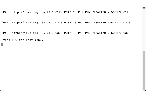
-
From the boot menu, enter the boot device number corresponding to the USB, and press Enter.
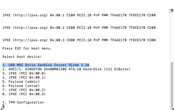
-
When the USB installer boot menu is displayed, proceed with the installation section below.
SSR1000 Series Devices
-
At the instruction in the terminal window:
Press <Tab> or <DEL> to enter Setup, do so.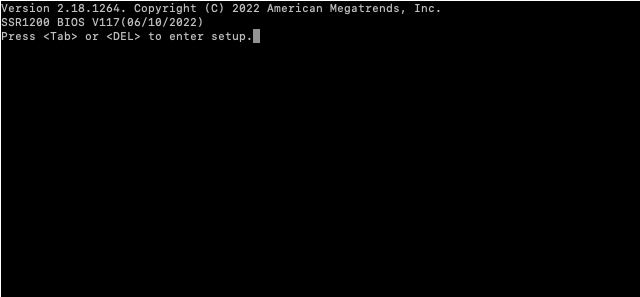
-
When the Setup Utility window appears, use the left and right arrow keys to navigate to the
Save & Exittab.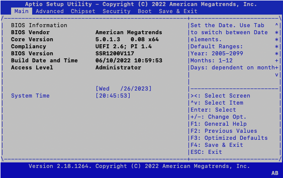
-
Use the up and down arrow keys to highlight the USB device in the Boot Override list.
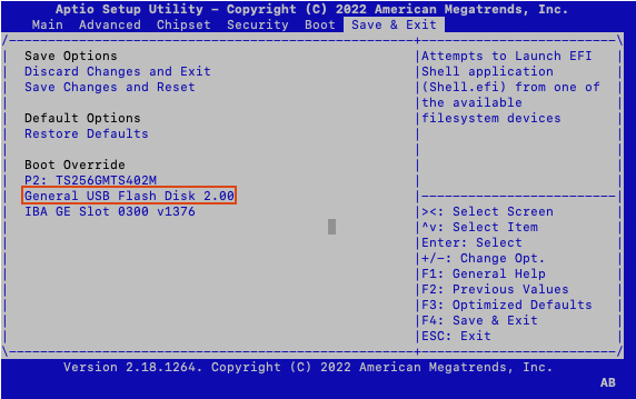
-
Press Enter to confirm boot from the USB device.
-
When the USB installer boot menu is displayed, proceed with the installation section below.
Router Installation
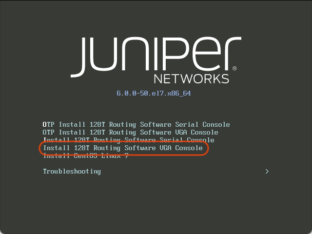
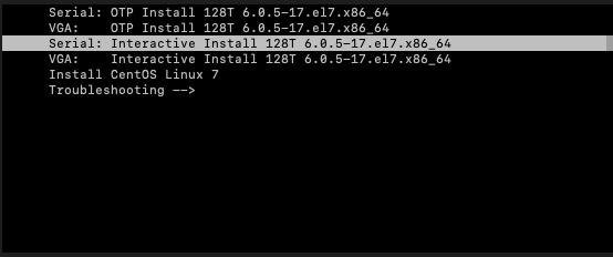
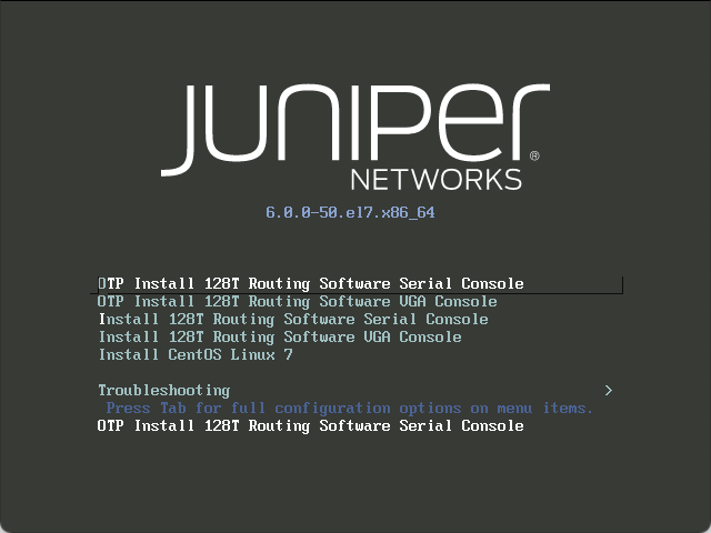
Upon boot, the following screen is displayed. The default selection is booting to the serial console (115200 baud). You must manually choose the installation process suited for your environment.
To install using the Interactive Installation, use the arrow keys to select either Install 128T Routing Software Serial Console or Install 128T Routing Software VGA Console. As noted earlier, this guide describes the installation process using the Interactive Installation, specifically using the VGA console.
FIPS Compliance
If you require FIPS compliance, skip to the steps in FIPS Enforcement Mode. When required, it is considered best practice to enable FIPS during installation.
Install via Serial Console
Use this option when running on hardware with no video chipset. It uses /dev/ttyS0 115200 baud as the serial console for interacting with the installer.
For serial console issues please refer to Serial Console Troubleshooting.
Because not all hardware has video support, booting to the serial console 115200 baud is the default, and is automatically selected after 30 seconds. When using the serial console, the terminal size is 80x25 - anything smaller may result in abnormal navigation behavior.
Selecting the wrong type of console (Serial or VGA) may result in garbled characters being displayed. If allowed to continue it will result in an incorrect installation. If the wrong console is selected, reboot the target system and select the correct line for the target hardware.
Install via VGA Console
Use this option when running on hardware that has onboard graphics chipsets. This installs SSR software using the GUI installer.
The procedure that follows here is the Interactive Install on the VGA Console.
Linux and SSR Install
After the Linux installation is complete, the SSR software installation begins. Note that this may take several minutes to complete (up to 40 minutes). After the installation has completed, the following screen is displayed:
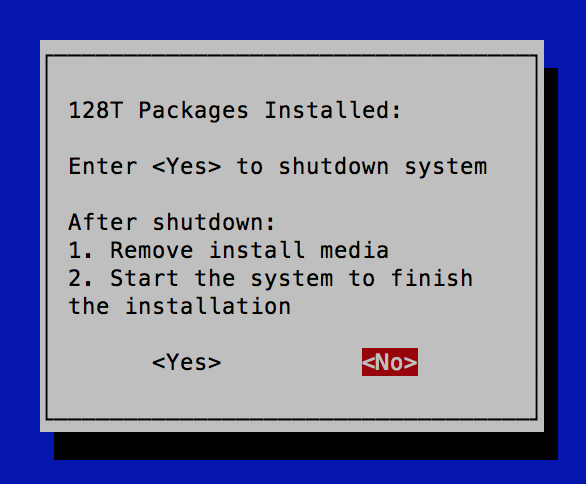
Select <Yes> to shut down the system. Remove the bootable media, then power the system up to complete the installation process.
In some cases, the screen above does appear, but becomes unresponsive after you select Yes. In this situation, you must manually power down the device (hold the power button for approximately 15 seconds), wait 10 seconds, and power it back up.
Initial Boot and Management Network Configuration
When the system boots from the Install 128T Routing Software... Interactive Installation work flow, the system asks whether to configure initial Linux Networking before the SSR Initializer is started.
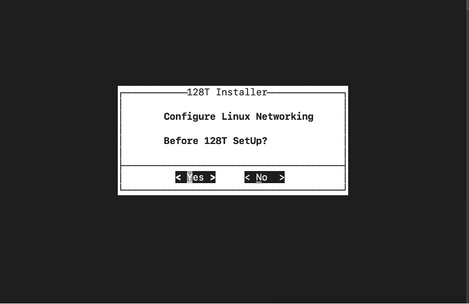
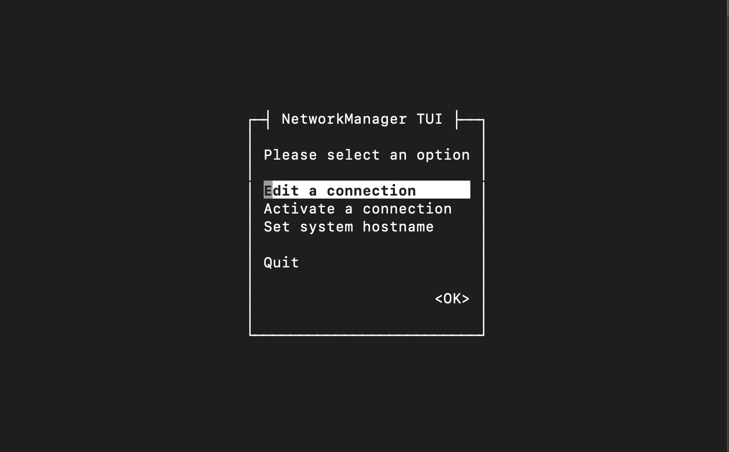
Selecting Yes launches the NMTUI application to perform an initial network interface setup.
Initialize the SSR Node
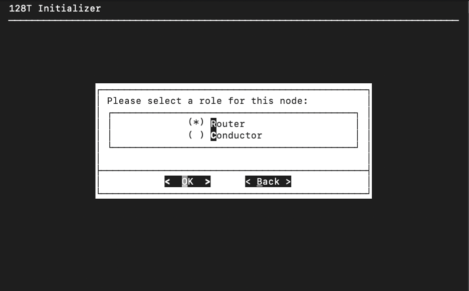
The SSR Initializer tunes your operating system, prepares the platform to run the SSR software, and creates the bootstrapping files necessary to load the software. The Initializer is launched on first boot.
- On the SSR Initializer wizard screen, use the space bar to select the Router role for the SSR node and press the Enter key to select OK.
- For SSR routers, you will be prompted for the IP address(es) of the conductor. If you have a conductor, enter the administrative IP address and the node will retrieve the configuration from the conductor. If you have only one conductor (i.e., a standalone conductor), leave the field labeled 2nd Conductor Address blank. If you have no conductors, choose Skip.
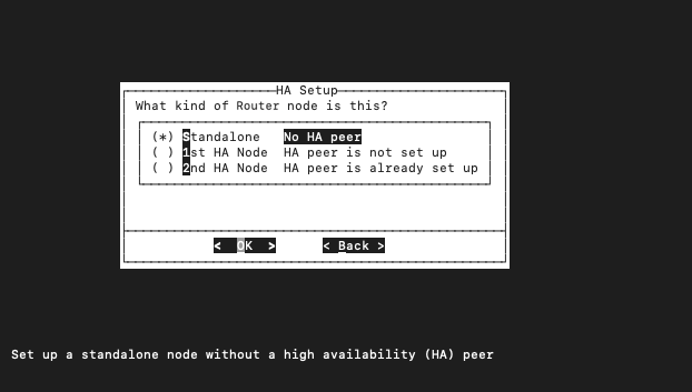
- When asked What kind of Router node is this?, select from the following options:
 )
)
-
Standalone: This router has no highly available peer, and is not currently planned for high availability.
-
1st HA Node: This router is the first node of a high availability pair. You will be prompted to provide the local IP address for this node. The 2nd HA node will contact this node at the address provided to synchronize state. Note: The 1st Node IP address must be reachable by the 2nd HA Node.
-
2nd HA Node: This router is the second node of a high availability pair, where the first node has been initialized. You will be prompted to provide the 1st Node IP address for this 2nd node that will be used to synchronize state. Note: The 2nd Node IP address must be reachable by the 1st HA Node.
- Enter the following system properties on the Node Info screen:
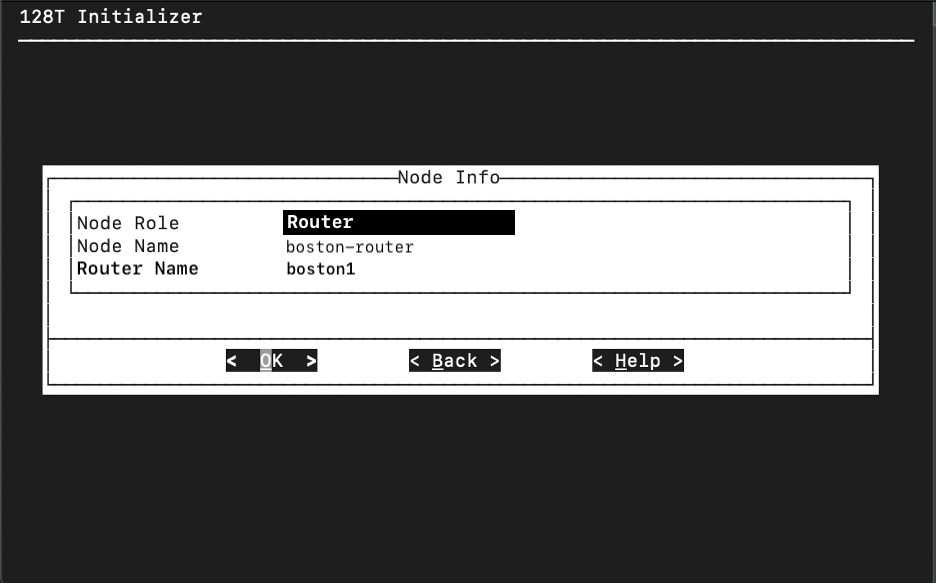
- Node Name: The name of the system within your SSR Router or Conductor, for example, boston_router. By default this field uses the Linux system's hostname.
Both routers and conductors can consist of one node (for standalone systems) or two nodes (for highly available systems).
- Router Name: The name of the router system as a whole. When referring to a running SSR software instance, it is identifiable by the full name of
nodeName.routerName; e.g.,boston_router-node1.router. The full system name is reflected in the PCLI prompt as discussed in the Document Conventions section of this document.
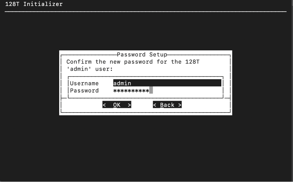
- On the Password Setup screen, create a password for the SSR Admin user. The administrator password must be at least 9 characters long, contain at least 1 uppercase letter, at least 1 lowercase letter, at least 1 number, cannot contain the username in any form, and cannot repeat characters more than 3 times. This operation is only performed on the standalone or first node in the HA peer.
Resetting a password requires entering the old password. If a password is lost or forgotten and the account is inaccessible, the account cannot be recovered. Please keep password records accessible and secure.
-
Press the Enter key to select OK. The Initializer performs a hardware compatibility check. The compatibility check may fail due to warnings or failure notices, which are displayed in the output script. If no failures are present, you can choose to continue with the installation even if multiple warnings exist. For information on why a specific test may have failed or generated a warning, contact Juniper Technical Support.
-
When prompted, select Yes to start the SSR.
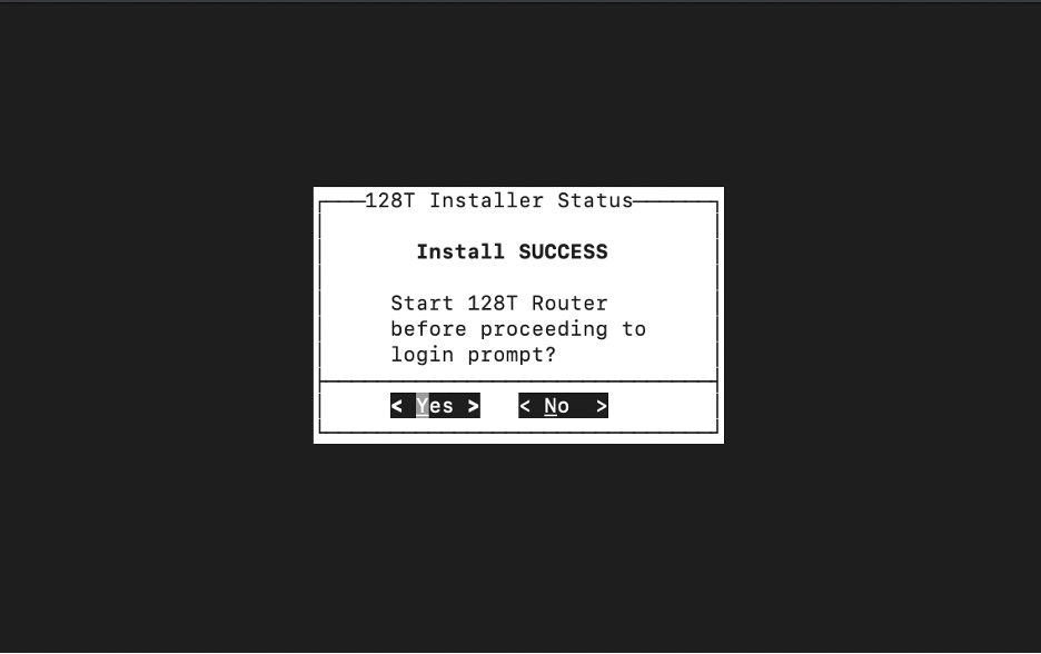
A system reboot is required.
Verify the Installation
After installing the SSR Software it is important to verify that the installation was completed successfully.
To Verify the SSR Installation:
-
Launch a command prompt window.
-
Execute the command:
sudo systemctl status 128T
-
When the service is listed as Active, log into the system as Admin using the system default password. By logging into the system, you have verified the installation.
-
Close the command prompt window.
-
Use a web browser to navigate to the IP address of the SSR GUI. For example;
https://192.168.1.25 -
Log in to the SSR GUI using the admin name and password you created earlier.
Change the Default Passwords after Installation
The following user accounts and passwords are created during the ISO installation process:
| Username | Password |
|---|---|
| root | 128tRoutes |
| t128 | 128tRoutes |
Change these passwords immediately. Log in to the Linux shell using the default password.
Oracle Linux Server 7.9
Kernel 4.18.0-553.16.1.el8_10.x86_64 on and x86_64

localhost login: t128
Password:
Last login Wed March 26 18:17:28 on pts/0
Then use the passwd command to change the root and t128 passwords.
[t128@test-router ~]$ passwd
Changing password for user t128
Changing password for t128
(current)Linux password:
New password:
Retype new password:
passwd: all authentication tokens updated successfully.
[t128@test-router ~]$ su -
Password:
[root@test-router ~]# passwd
Changing password for user root.
New password:
Retype new password:
passwd: all authentication tokens updated successfully.
[root@test-router ~]#
FIPS Enforcement Mode
If you require strict FIPS compliance, the fips=1 kernel option must be added to the kernel command line during system installation to ensure that key generation is done with FIPS approved algorithms and continuous monitoring tests in place.
- Use up/down keys to highlight the desired install mode.
-
Press TAB to edit the configuration.
-
Add
fips=1to the end of thevmlinuzparameters.
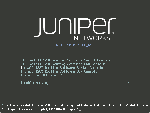
- Press Enter to start the install.
Return to Linux and SSR Install to continue with the installation.