Configuring Ethernet Over SVR for Active/Standby
EoSVR is a point-to-point L2 service that provides session resiliency even during a failover between different underlying networks. However, there may be cases where you also require redundancy at the service level when using L2 services in the network.
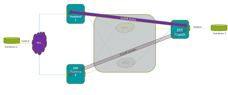
For example, in a network deployment where there are no loop detection mechanisms available, the EoSVR Active Standby configuration gives you the ability to configure two different endpoints on the P2P L2 service, while making sure only one is active at a time. In the configuration example below, VLAN A needs to be extended so that End Device 2 can be reached from either head-end, typically deployed in two different datacenters.
Configuration Example
The EoSVR Active/Standby feature relies on the standard EoSVR functionality. To configure Active/Standby, the same LAN interface IP address needs to be defined on both head-ends.
Note that the peer service routes are generated by the conductor when an EoSVR service route is configured for each service. They are shown here for completeness.
Branch
name               Lan1
global-id          27

ethernet-over-svr name     br6
ethernet-over-svr enabled  true

ethernet-over-svr peer 169.254.50.5 SSR_HE1 ip-address  169.254.50.5
ethernet-over-svr peer 169.254.50.5 SSR_HE1 peer        SSR_HE1
tenant   branch.tenant1

address 169.254.50.6 ip-address     169.254.50.6
address 169.254.50.6 prefix-length  24
Headend 1
name               Lan
global-id          30

ethernet-over-svr name     br7
ethernet-over-svr enabled  true

ethernet-over-svr peer 169.254.50.6 SSR_BRANCH ip-address  169.254.50.6
ethernet-over-svr peer 169.254.50.6 SSR_BRANCH peer        SSR_BRANCH
tenant             he1.tenant1

address 169.254.50.5 ip-address     169.254.50.5
address 169.254.50.5 prefix-length  24
Headend 2
name               lan_l2
global-id          10

ethernet-over-svr name     br5
ethernet-over-svr enabled  true

ethernet-over-svr peer 169.254.50.6 SSR_BRANCH ip-address  169.254.50.6
ethernet-over-svr peer 169.254.50.6 SSR_BRANCH  peer        SSR_BRANCH
tenant             he2.tenant1

address 169.254.50.5 ip-address     169.254.50.5
address 169.254.50.5 prefix-length  24
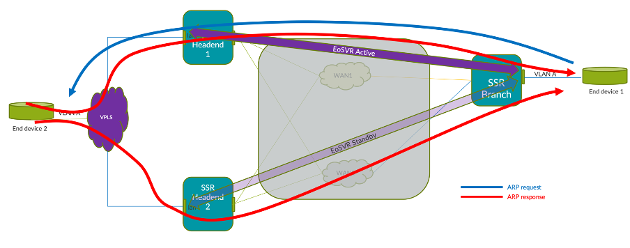
How It Works
EoSVR A/S relies on the SSR to send broadcast traffic using only one of the defined services (either the active or the backup), even though traffic is received from both.
In a standard EoSVR configuration there are typically two routers; R1 and R2. EoSVR is configured on the LAN of R1 and R2. There is a WAN connection between R1 and R2, and they communicate via SVR. Since EoSVR is configured on the LAN of R1 and R2, they both act as a virtual LAN. There are 2 services that are configured:
-
A service from R1 to R2 so that L2 and IP packets can go from R1 to R2. This service has the IP address of the interface with EoSVR enabled on R2. The service route on R2 is an EoSVR bridge.
-
A service for packets from R2 to R1 where the service address is the IP of the EoSVR interface on R2.
For EoSVR Active/Standby, all of the above holds true, but we now have R1 talking to Headend 1 and Headend 2. This means there will be:
- one service for H1's EoSVR interface IP
- one service for H2's EoSVR interface ip
- one service for R1's EoSVR IP
In order to demonstrate the configuration, let's assume the scenario in the figure above.
Step 1: Configure LAN Interfaces
Configure the LAN network interfaces:
-
Both head-ends have their respective EoSVR bridges configured with the same IP address in the network interface and on the peer with the branch EoSVR bridge.
-
The branch EoSVR bridge peering is configured with the IP address used in both head-ends.
Branch
name               Lan1
global-id          27

ethernet-over-svr name     br6
ethernet-over-svr enabled  true

ethernet-over-svr peer 169.254.50.5 SSR_HE1 ip-address  169.254.50.5
ethernet-over-svr peer 169.254.50.5 SSR_HE1 peer        SSR_HE1
tenant   branch.tenant1

address 169.254.50.6 ip-address     169.254.50.6
address 169.254.50.6 prefix-length  24
Headend 1
name               Lan
global-id          30

ethernet-over-svr name     br7
ethernet-over-svr enabled  true

ethernet-over-svr peer 169.254.50.6 SSR_BRANCH ip-address  169.254.50.6
ethernet-over-svr peer 169.254.50.6 SSR_BRANCH peer        SSR_BRANCH
tenant             he1.tenant1

address 169.254.50.5 ip-address     169.254.50.5
address 169.254.50.5 prefix-length  24
Headend 2
name               lan_l2
global-id          10

ethernet-over-svr name     br5
ethernet-over-svr enabled  true

ethernet-over-svr peer 169.254.50.6 SSR_BRANCH ip-address  169.254.50.6
ethernet-over-svr peer 169.254.50.6 SSR_BRANCH  peer        SSR_BRANCH
tenant             he2.tenant1

address 169.254.50.5 ip-address     169.254.50.5
address 169.254.50.5 prefix-length  24
Step 2: Configure Neighborhoods to determine active and standby services
In order to control which service is active and which is standby, two different neighborhoods are defined and vectors applied. Let's say you want to prefer H1 for all packets from R1 to the head-end. Only in a situation where H1 fails or all paths to H1 fail, will we want to send packets to H2.
Configure the neighborhood and the vectors; For the service towards the head-end (the H1-H2 service), set the vector values to prefer the paths to H1 (primary path), and then to H2 (secondary path).
Branch
name                   wan1
global-id              25
conductor              false

neighborhood wan1_standby name    wan1_standby
neighborhood wan1_standby vector  wan1_standby

neighborhood wan1_active name    wan1_active
neighborhood wan1_active vector  wan1_active
Headend 1
name                   wan1
global-id              7

neighborhood wan1_active name      wan1_active
neighborhood wan1_active topology  hub
neighborhood wan1_active vector    wan1_active
Headend 2
name                   wan1
global-id              28

neighborhood wan1_standby name      wan1_standby
neighborhood wan1_standby topology  hub
neighborhood wan1_standby vector    wan1_standby
Step 3: Configure Services
If you are not familiar with configuring L2 and L3 services, please refer to Create a Service for Ethernet Over SVR.
Create the service using a branch-to-head-end direction.
L2 service
name            l2_service
security        unencrypted

transport udp protocol    udp

transport udp port-range 1281 start-port  1281
address         169.254.50.5

access-policy branch.tenant1 source  branch.tenant1
service-policy  customer_L2
L3_service
name                  L3_service
security              unencrypted

transport tcp protocol  tcp

transport udp protocol  udp

transport icmp protocol  icmp
address               0.0.0.0/0

access-policy branch.tenant1 source  branch.tenant1
service-policy        customer_L2
share-service-routes  true
Headend 1
name          L2_service_SR
service-name  L2_service
bridge-name   br7
name          L3_service_SR
service-name  L3_service
bridge-name   br7
Headend 2
name          L2_service_SR
service-name  L2_service
bridge-name   br5
name          L3_service_SR
service-name  L3_service
bridge-name   br5
Step 4: Configure the Service Policy
When you configure the service policy, make sure session-resiliency is set to revertible failover. Configure the vector list according to the active / standby priorities. For information about configuring vectors and priorities, refer to the Configuration Element Reference.
name                  customer_L2
vector wan1_active name  wan1_active
vector wan1_standby name  wan1_standby
session-resiliency    revertible-failover
peer-path-resiliency  true