Step 2: Install SSR Software and Initialize the Hub Router
This step boots the router VM from the SSR ISO, installs the software, and uses the web-based initialization interface to configure the VM as a conductor-managed branch router.
Install SSR Software
-
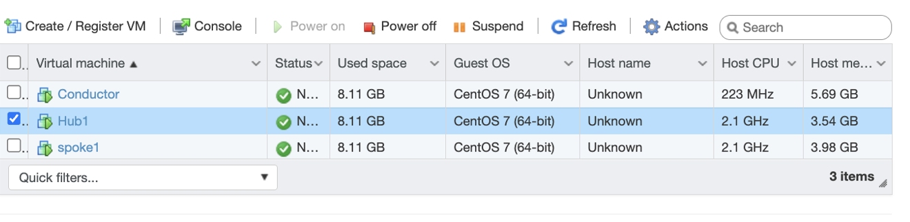
Select the new router VM in the ESXi Navigator and click the Play (Power On) button.
-
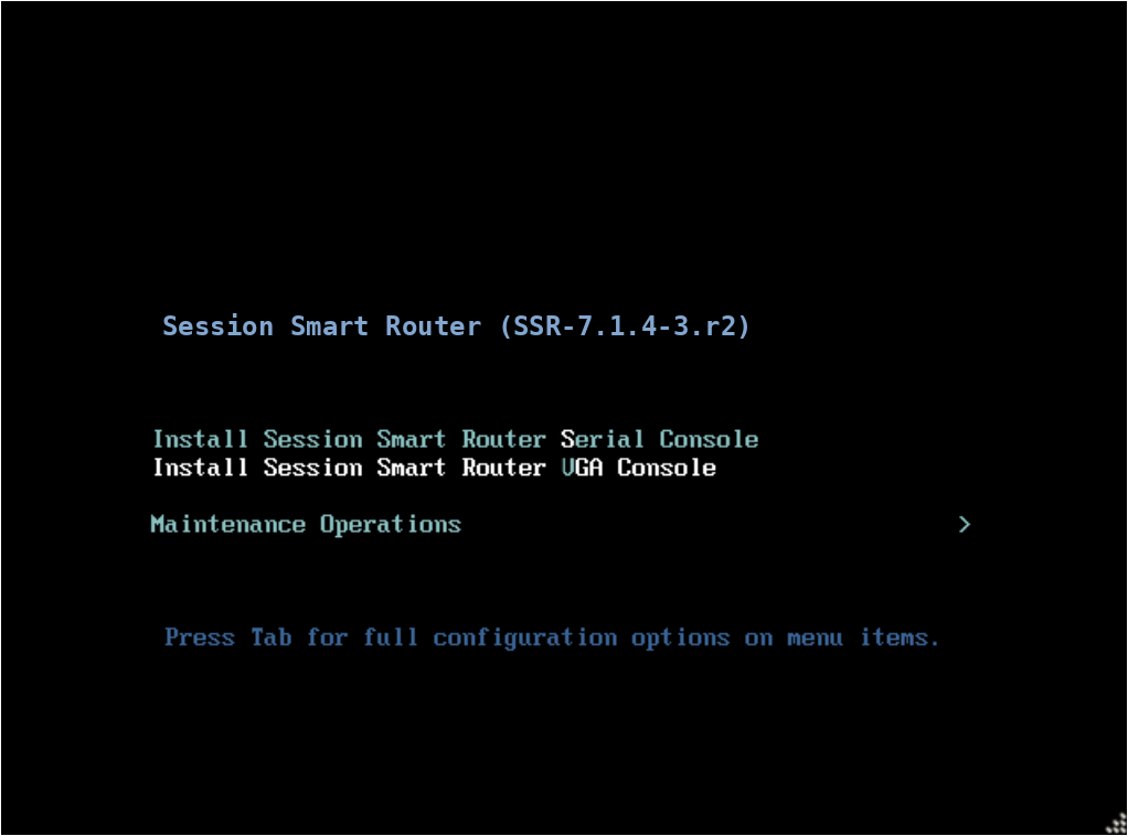
At the Install menu, use the arrow keys to select VGA Console.
-
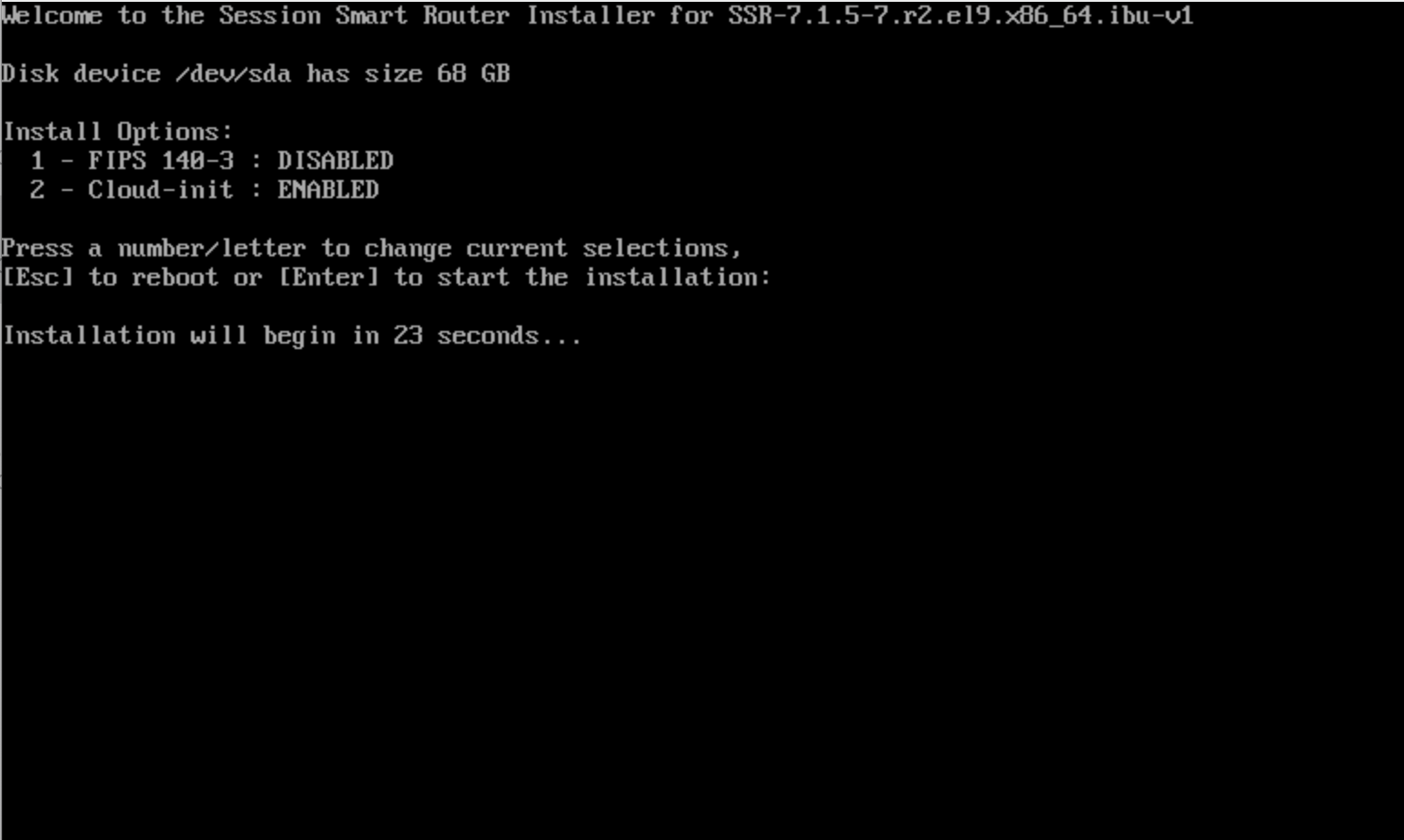
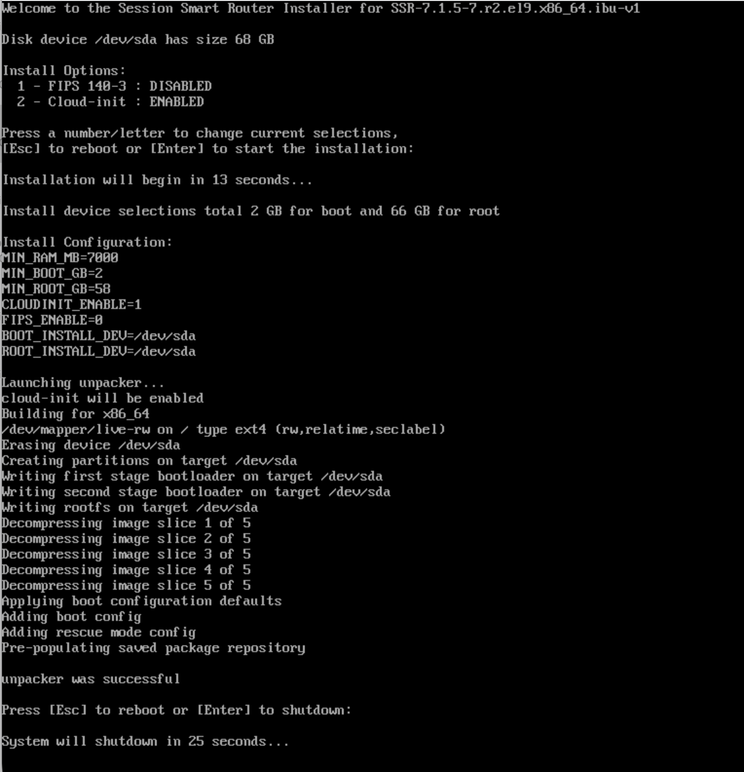
If you require FIPS mode, select Install Option 1 and press Enter. If FIPS is not required, press Enter without selecting an option. The download and installation begins.
noteIDP is not compatible with systems running in FIPS 140-3 mode, including Common Criteria or JITC deployments. If you plan to enable IDP, do not enable FIPS mode. See IDP Troubleshooting for information on disabling FIPS mode if needed.
Additionally, please note that FIPS mode disables BGP MD5 authentication.
-
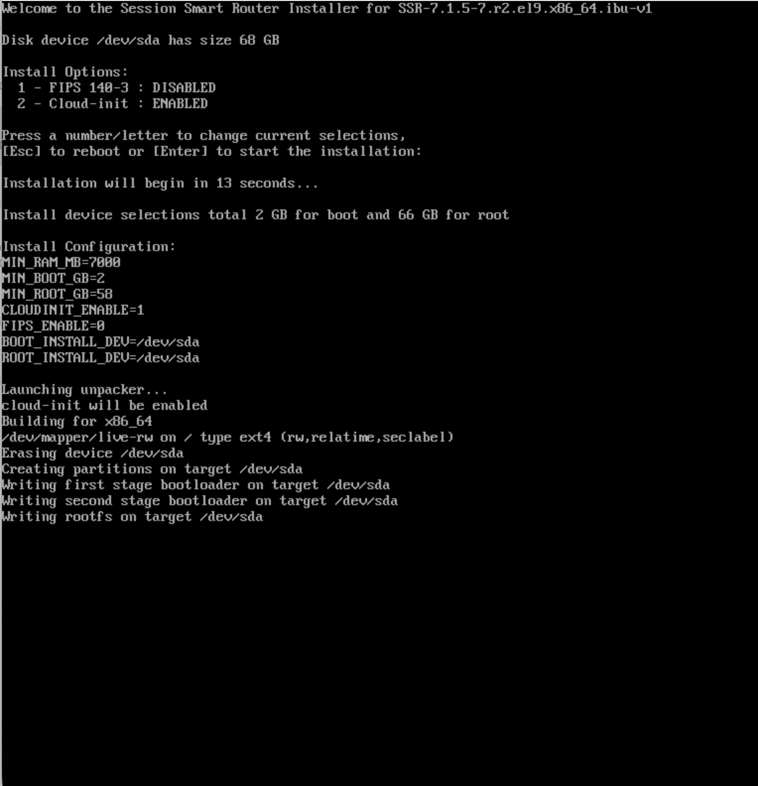
The installation runs to completion automatically. This may take approximately 15–20 minutes.
-
When prompted to reboot, allow the VM to shutdown.
Apply VLANs to the Hub
These steps configure VLANs on the router.
-
In the VM in the ESXi Navigator, start the Hub1 Virtual Machine.
-
Select Console and login using the root credentials.
importantBeginning with SSR 7.2.4-R2, a new installation requires that the default
root,t128, andadminpasswords be reset upon first login. Complete the password-change prompts before running the commands below. Once the password has been reset, use the new password for subsequent logins. See Default Passwords and First Login for additional information. -
From the linux prompt run the command
su adminto enter the SSR CLI.-
Run
show network-interface | more. This will display the DHCP IP addresses.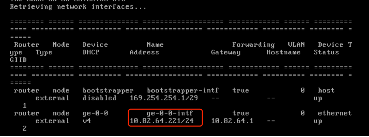
-
Locate the ge-0-x interfaces, and make a note of the IP address. Example:
ge-0-0 =00:0c:29:6c:32:c1ge-0-1 =00:0c:29:6c:32:a3ge-0-2 =00:0c:29:6c:32:cbge-0-3 =00:0c:29:6c:32:ad
-
-
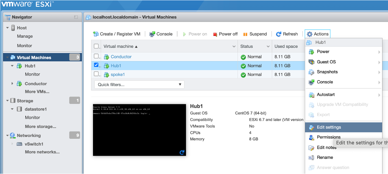
From the Hub VM in the ESXi Navigator, select Actions and then Edit Settings.
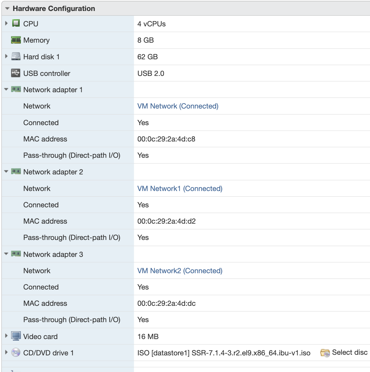
In the Hardware Configuration window, expand each network adapter to see the MAC address associated with the Network adapter.
-
Use the diagram below and the interface names for each MAC address, to associate the correct network VLAN with each interface. Use the following VM VLANs: VLAN1 (ge-0-0, the management port), VLAN67 (ge-0-1), VLAN3 (ge-0-2), and VLAN4 (ge-0-3). The Network Adapter, MAC address and ge-0-x interface name(s) should match based on the MAC addresses previously determined. Save when complete.
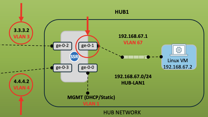
Example:
ge-0-0 =00:0c:29:6c:32:a3 = Adapter 1 (VLAN1)
ge-0-1 =00:0c:29:6c:32:ad = Adapter 2 (VLAN67)
ge-0-2 =00:0c:29:6c:32:b7 = Adapter 3 (VLAN3)
ge-0-3 =00:0c:29:6c:32:c1 = Adapter 4 (VLAN4)
- Click Save.
Initialize the Router
-
In the VM in the ESXi Navigator, select the Hub1 Virtual Machine, and click Power On.
-
Click Console and login using the root credentials.
- Username:
root - Password: Your current root password or
128tRoutesif the factory password has not yet been reset.
The system takes a few minutes to start up.
- Username:
-
Run the command
su adminto enter the PCLI.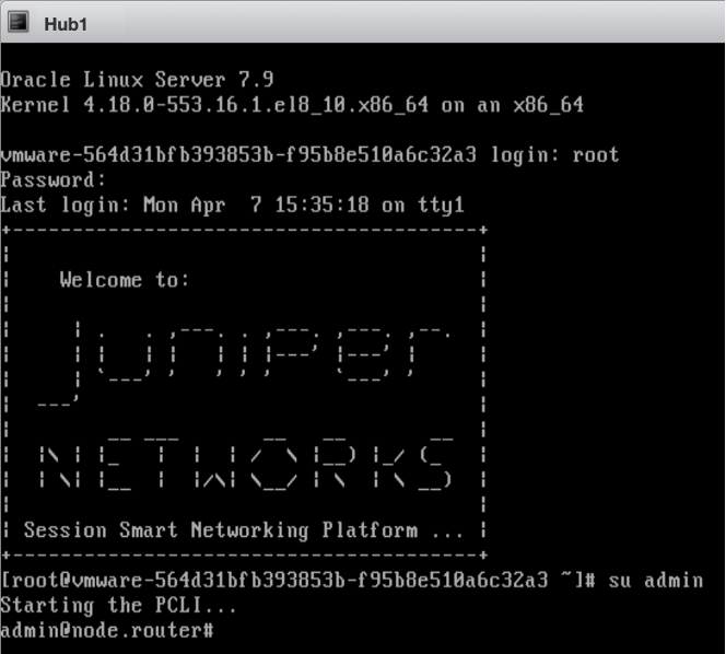
-
Enter the following command to connect the Hub1 router to the conductor:
initialize conductor-managed router-name Hub1 conductor-ip <conductor-ip-address>Wait for the device to show
Device successfully initialized. This step may take several minutes to complete.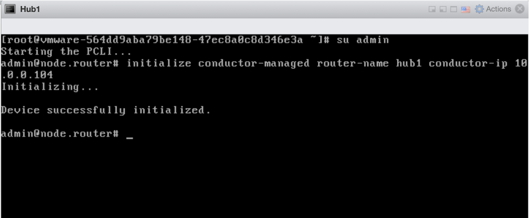
Let’s go to the Conductor GUI, add this router, and connect it for communication to the Conductor.
-
Open a browser tab on your computer and navigate to your VMWare conductor;
https://192.168.100.10and initiate a web session to the conductor GUI.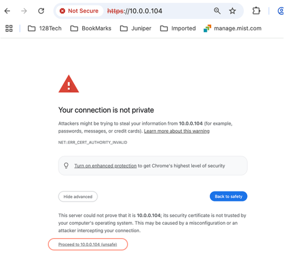
-
Accept the self-signed certificate warning, and login using the username and the password you set earlier.
-
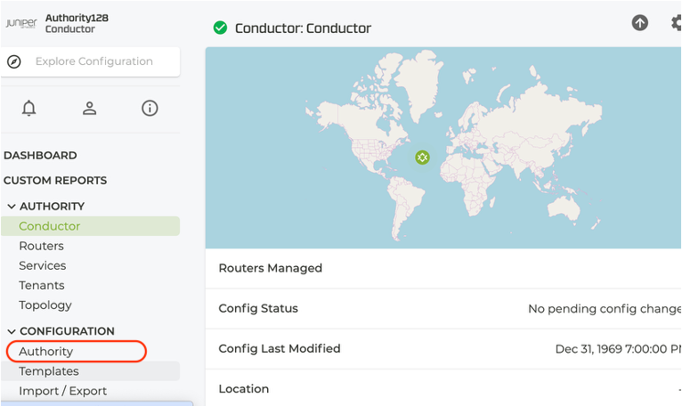
In the Conductor GUI, click on Authority.
-
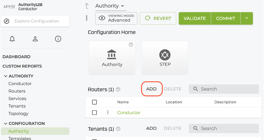
At the top of the list of Routers, select ADD.
-
Enter the router
Hub1and click Save.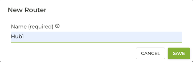
Add a Location for the Router
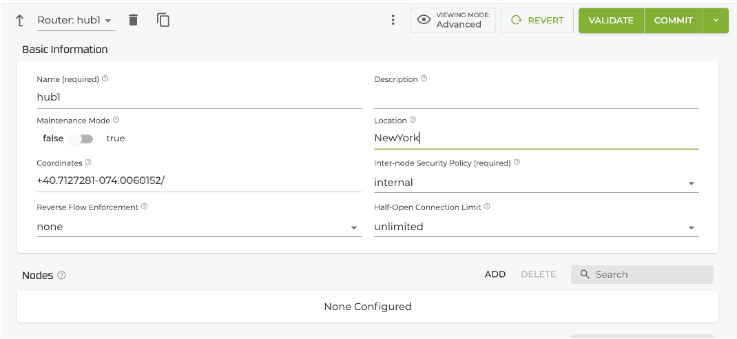
After adding the router name, let’s add the location of this router. For this example, we'll use New York.
-
In the Router Basic Information screen, enter New York under Location.
-
If you have the location coordinates (for this example, enter the following exactly:
+40.7127281-074.0060152/), you can enter them. -
Under Inter-node Security Policy, select
Internal. -
Below the Basic Info screen, click ADD next to Nodes.
-
The New Node dialog is displayed - enter
node0.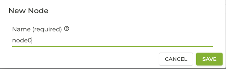
-
Click Save. The Node screen appears.
Set the Asset ID
The Asset ID allows the hub and conductor to fully connect, and allows the conductor to configure and control the hub router.
-
On the Node screen, verify the Node Name is
Node0, set the Associated Asset ID toHub1, and set the Role toCombo.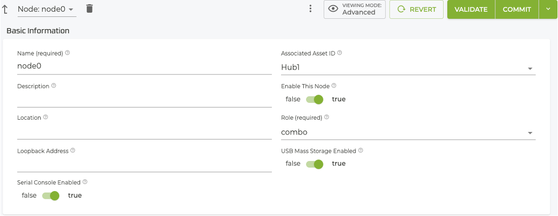
-
Click COMMIT.
If you see a Review Commit Warning, click Proceed and Commit . Your router is now bound to the conductor, sharing keys and trust. Connectivity will not be available for roughly 8-10 minutes, until full synchronization between the hub and conductor. When the Routers page displays
Synchronized, the router is ready to be configured from the conductor.
Next Step
Proceed to Step 3 — Find VM NIC PCI Addresses.