SNMP - Configuration
Overview
The following are the high level steps for configuring SNMP. Each procedure is detailed below.
-
Configure KNI Interface at both hub and spoke SSRs
-
Enable SNMP Server in Router System Settings at both hub and spoke SSRs
-
Configure Global Services: snmp (polling) and snmp-trap
- A unique Service for snmp polling for every hub and spoke SSR
- One common Service snmp-trap
-
Configure Service Routes at both hub and spoke SSRs
Configuration
The procedures below use the GUI to create the configuration, and assume the following:
- The SNMP Manager is located behind the hub SSR
- Both spoke and hub SSRs are not located behind any firewall or NAT devices
Configure the KNI Interface
For additional information about the configuration of KNI interfaces, see Kernel Network Interfaces.
-
From the Authority, navigate to the Router > Node > Device Interface.
-
Under the Device Interface, click ADD.
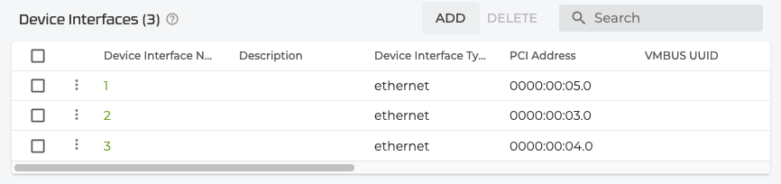
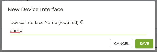
- In the New Device Interface pane, enter a name for the device interface.
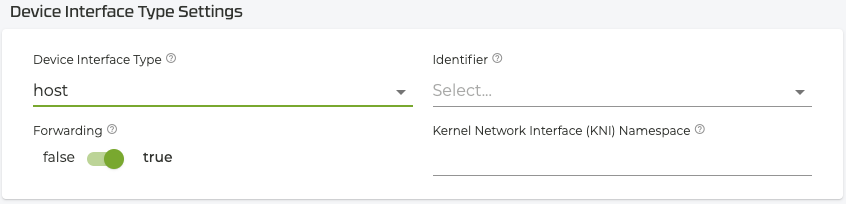
- Set the Device interface type as Host.
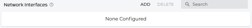
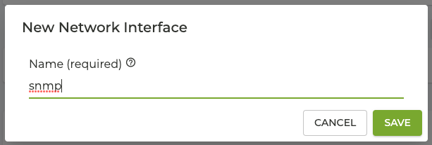
- Scroll down to Network Interfaces. Click on ADD to add a new network interface for the SNMP device interface.
- Enter
snmpas the name of the network interface and click SAVE.
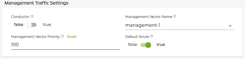
- Under Management Traffic Settings, define a dedicated management vector. This vector should be associated with the management interface.
- Enter the name
- Set the priority to 100
- Enable a default route
- Scroll down to Interface Addresses, click ADD and enter the IP address of the network interface and click SAVE.
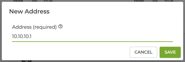
- Configure the KNI IP subnet. Every SSR running SNMP must be configured with a unique, routable IP subnet. Choosing /30 maximizes the number of subnets in a chosen IP block.
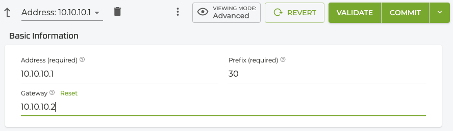
It is important that this address is specified as the address to be polled by the SNMP Manager. The Gateway IP address is also used by the SSR to automatically create an interface at the Linux level later in this procedure.
-
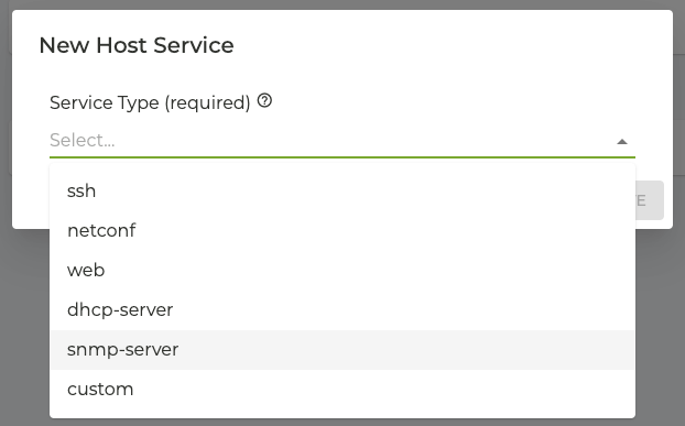
Under Host Services, click ADD.
-
Under Service Type, select snmp-server.
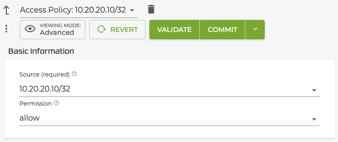
- Under Access Policies, click add, and enter the IP address for the SNMP manager.
Configure Router System Settings
Return to the Router level, and scroll down to the Router Settings.
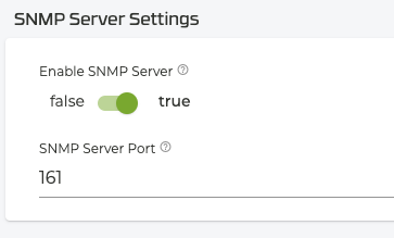
- Click the System Settings button.
- Scroll down to the SNMP Server Settings and Enable the SNMP Server.
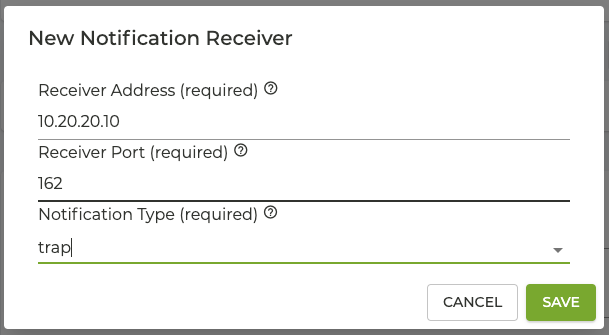
- Under SNMP Notification Receivers, click ADD, enter the IP address of the SNMP Manager, and set the Notification Type to trap.
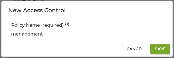
- Return to the router system settings, scroll down to the SNMP Access Control Policies and click ADD.
- Enter the
managementas the new Access Control Policy name and click SAVE.
- In the SNMP Access Control Policies pane, enter the Permitted Client Host IP address.
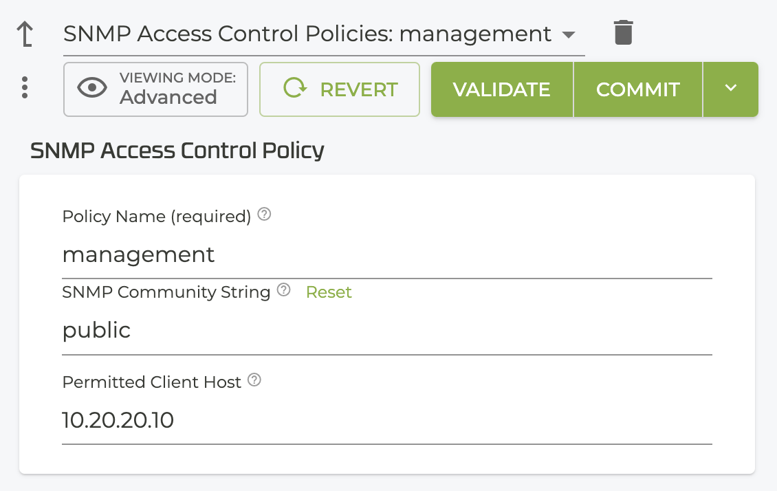
- Click Validate, then Commit.
A new interface is created at the Linux level bearing the same name and gateway IP of the snmp interface created earlier. The gateway IP is the address that the SNMP Manager will be polling.
Configure Global Services
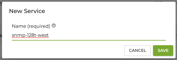
At the Authority Level, scroll down to Services, and click ADD.
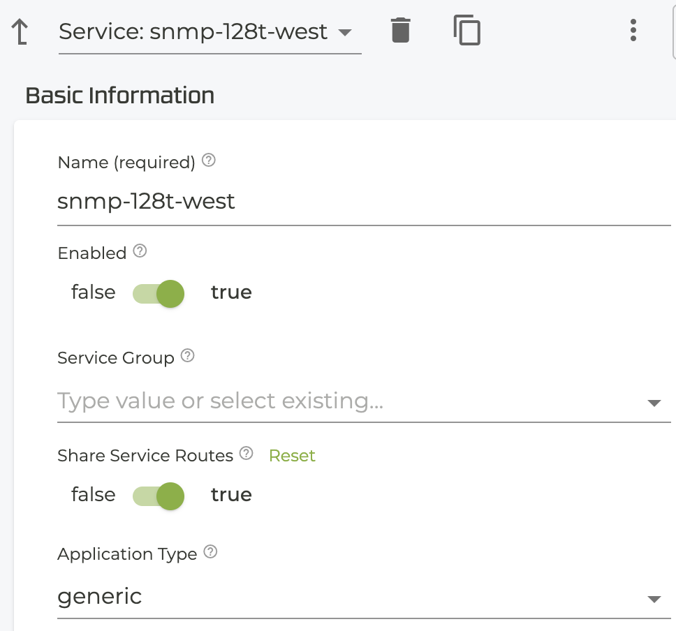
- Enter a name for the new service; in this case, the service name is
snmp-<SSR-name>. Create a service for each SSR. This service is used for polling of individual SSRs.
- In the Basic Information panel, verify that the Share Service Routes toggle is set to true (default).
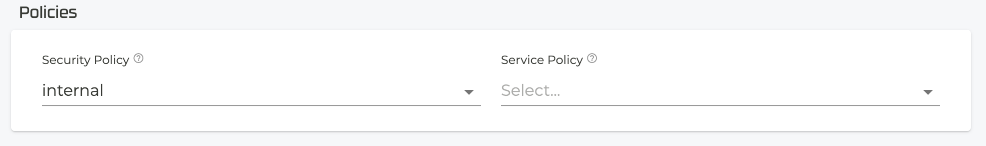
- Scroll down to Policies, and set the Security Policy to internal.
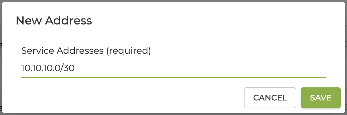
- Scroll back up to Service Addresses and enter the KNI Subnet for the SSR configured in step 9 of the KNI Interface process.
Configure the SNMP-trap
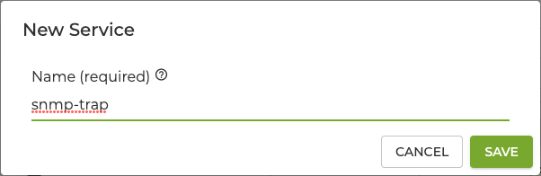
Return to the Authority level, scroll down to Services, and click ADD.
- Name the service snmp-trap. This service is used for traps from all SSRs.
- In the Basic Information panel, verify that the Share Service Routes toggle is set to true (default).
- Scroll down to Policies, and set the Security Policy to internal.
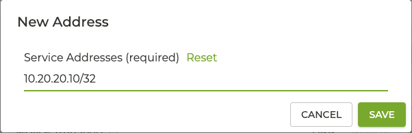
- Scroll back up to Service Addresses, click ADD, and enter the IP address of the SNMP manager.
- Click Validate, then Commit.
Configure the SNMP Service Routes
The SNMP Service routes are used for polling each SSR by the SNMP manager.
SNMP Service Route
This procedure creates the service route used for SNMP polling, and must be repeated at each SSR to be polled by the SNMP Manager.
- From the Authority level, select the router.
- Scroll down to Service Routes and click ADD.
- Enter the New Service Route name;
snmpand click SAVE. - In the Service route Information pane, choose the
snmp-<service-name>service name created earlier.
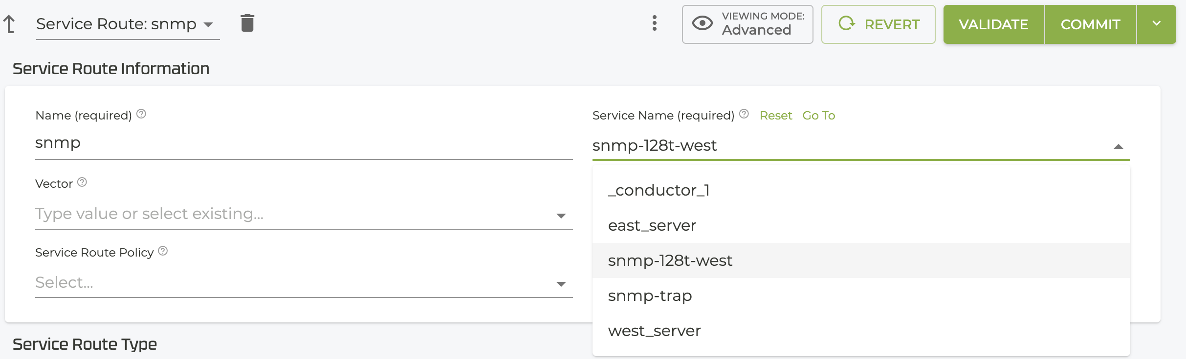
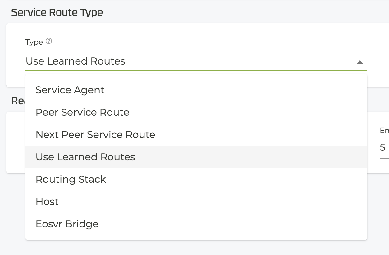
- Under Service Route Type, select Use Learned Routes from the drop down.
- Click Validate, then Commit.
Return to the Router level, and select the Hub SSR. You can see the service route is automatically generated at the SNMP Manager.
SNMP-trap Service Route
- From the Router level, and select Service Routes.
- Click ADD.
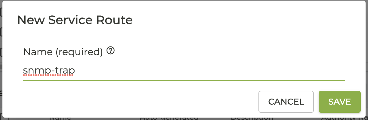
- Enter a new Service Route name,
snmp-trapand click SAVE.
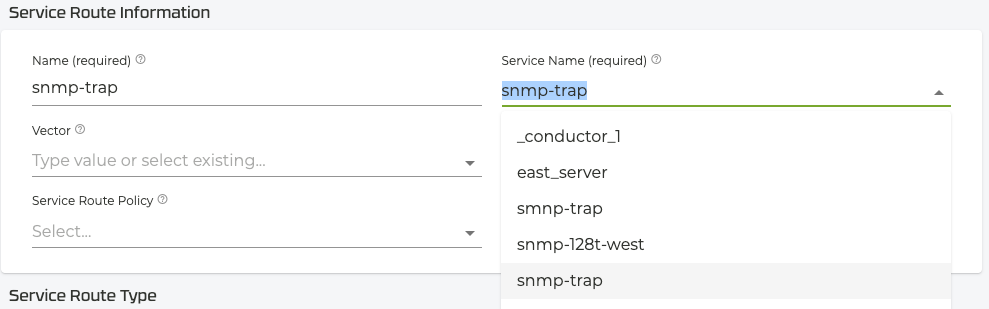
- In the Service route Information pane, choose the
snmp-trapservice route created earlier.
- Under Service Route Type, select Use Learned Routes from the drop down.
- Click Validate, then Commit.
Return to the Router level, and select the Spoke SSR. You can see the service route is automatically generated where the snmp traps are generated.