Configuring Dual Router High Availability using iBGP
The SSR provides significant flexibility for high availability configurations. Like traditional routers, the SSR software can be deployed as a single router instance on multiple platforms, with high availability configured in a dual router configuration. Additionally, the SSR can deploy multiple software instances (referred to as nodes) within the same single installation, providing high availability across router nodes.
The release of the 5.4 software includes VRRP as a configuration option as well as a new service route parameter, enable-failover, that provides stateful failover on the dual node HA configuration. For configuration options using VRRP, please refer to Configuring Dual Router High Availability and VRRP
Dual Router High Availability
This document covers dual router high availability using iBGP - two instances of the SSR software each configured as separate routers. This is characterized by:
- An iBGP interface shared between the two devices in lieu of a "fabric" interface in the dual node deployment.
- No
shared-phys-address(and hence no shared interfaces) between the two devices. Interface protection in a dual router HA deployment is accomplished using traditional routing protocols (Layer 3) rather than IP/MAC takeover (Layer 2). - No state synchronization between the two devices (and hence no "HA link"). While this improves overall performance for the routers (since there is no overhead incurred due to state synchronization), the implication is that there are some capabilities not supported in this design. See Unsupported Features, below.
Unsupported Features
When deploying two nodes in a dual router high availability deployment, several features that rely on synchronized state between nodes are no longer available.
- Source NAT. When source NAT is enabled, a system will allocate ephemeral ports on its egress interface as sessions leave the SSR router. Because there is no state synchronization between the two nodes in this deployment model, these ephemeral ports are not shared. Thus, if the active node fails and traffic starts transiting its counterpart, the source NAT allocation on the newly active system will be different. This will impact application flows.
- Shared interfaces. A router node cannot perform gratuitous ARP takeover of an interface from another, distinct router node.
Design Constraints
Due to the way that dual router high availability operates without state synchronization, in the event of a failure to one router in a pair, all traffic will be sent to the counterpart router (once routing converges). The now-active router does not have a shared database to reconstruct session state; it will receive mid-session packets (from the client's and server's perspectives) and need to set up forwarding state.
For this reason, services that leverage a dual router HA pair must reference a service-policy that has transport-state-enforcement allow configured for TCP packets. Otherwise, mid-session TCP packets cause the SSR device to send a TCP RST to the sender.
Design Overview
Dual router high availability uses an inter-router iBGP connection to forward packets.
It is possible to configure multiple inter-router connections for added resiliency if there are spare physical connections available between the two routers.
The sample high level topology we will discuss in this document is as follows:
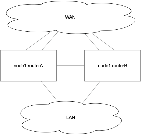
Notes about the Topology
In this sample configuration, each of the two routers (routerA and routerB) have two WAN interfaces and one LAN interface. Between them is an interconnect cable; for collocated routers, this is a simple "crossover" cable between the two systems.
Routing Overview
Routing within the dual router redundancy model must be configured manually — that is, individually on each system. This consists of two components:
- Each router uses BGPoSVR to exchange routes with the other.
- For services that use
peer-type service-routesto reach another SSR instance, these service-routes must include the complementary router as an additionalnext-peer. Meaning each router in the HA pair will point to thenext-peerSSR as well as anext-peerfor one another.
Sample Configuration
Each of the two routers that comprise the highly available pair will be configured similarly. Here is our routerA:
admin@node1.bernstein# show config run auth router routerA

config

    authority

        router  routerA
            name                 routerA
            router-group         headend-datacenter1
            inter-node-security  internal

            node                 node1
                name                  node1
                asset-id              797b06cb-2187-406a-a933-4e93fc991fb0
                description           "routerA standalone node"
                role                  combo
                forwarding-core-mode  automatic

                device-interface      eno1
                    name               eno1
                    type               ethernet
                    pci-address        0000:00:01.0
                    forwarding         true

                    network-interface  interrouter
                        name                   interrouter
                        global-id              10

                        neighborhood           dc1-interrouter
                            name               dc1-interrouter
                            peer-connectivity  bidirectional
                            topology           mesh
                        exit
                        inter-router-security  unencrypted

                        address                169.254.1.28
                            ip-address     169.254.1.28
                            prefix-length  31
                        exit
                    exit
                exit

                device-interface      eno2
                    name               eno2
                    description        "LAN interface"
                    type               ethernet
                    pci-address        0000:00:02.0
                    forwarding         true

                    network-interface  lan
                        name         lan
                        global-id    11
                        description  "Data center LAN"
                        vlan         0

                        address      10.0.128.2
                            ip-address     10.0.128.2
                            prefix-length  24
                        exit
                    exit
                exit

                device-interface      eno3
                    name               eno3
                    description        "WAN interface 1"
                    type               ethernet
                    pci-address        0000:00:03.0
                    forwarding         true

                    network-interface  wan1
                        name         wan1
                        global-id    12
                        description  "WAN 1"
                        vlan         0

                        address      198.51.100.2
                            ip-address     198.51.100.2
                            prefix-length  24
                        exit
                    exit
                exit

                device-interface      eno4
                    name               eno4
                    description        "WAN interface 2"
                    type               ethernet
                    pci-address        0000:00:04.0
                    forwarding         true

                    network-interface  wan2
                        name         wan2
                        global-id    13
                        description  "WAN 2"
                        vlan         0

                        address      203.0.113.2
                            ip-address     203.0.113.2
                            prefix-length  24
                        exit
                    exit
                exit
            exit

            routing              default-instance
                type              default-instance

                interface         lo1
                    name        lo1
                    ip-address  169.254.2.1
                exit

                routing-protocol  bgp
                    description   "Dual router HA iBGP"
                    type       bgp
                    local-as   64512
                    router-id  169.254.2.1

                    neighbor   169.254.2.2
                        neighbor-address  169.254.2.2
                        neighbor-as       64512
                        shutdown          false

                        timers
                            connect-retry                   30
                            minimum-advertisement-interval  30
                        exit

                        transport
                            passive-mode   false

                            local-address
                                routing-interface  lo1
                            exit
                        exit

                        address-family    ipv4-unicast
                            afi-safi       ipv4-unicast
                            next-hop-self  true
                        exit
                    exit
                exit
            exit
        exit
    exit
exit
Routing Configuration
The dual router high availability design does not synchronize state between routers. Instead, the two devices exchange reachability information using iBGP. This is implemented on the SSR using BGP over SVR (BGPoSVR), as shown in the sample configuration.
In our sample configuration we use device-interface eno1 as our iBGP link. The sample uses link-local IP addresses, presuming that the two nodes are located next to one another in the same data center. The neighborhood dc1-interrouter configuration is provisioned on routerB, and indicates to conductor that the two devices are mutually reachable. These pieces combined with the loopback interfaces are what creates the peering relationship, the services, and the service-routes in support of BGPoSVR.
The iBGP also interacts with other routing protocols to exchange reachability information with one another. For example, you may redistribute ospf into this iBGP, so that each device is aware of the other's reachability, as shown here:
                routing-protocol  bgp
                    description   "Dual router HA iBGP"
                    type          bgp
                    local-as      64512
                    router-id     169.254.2.1

                    neighbor      169.254.2.2
                        neighbor-address  169.254.2.2
                        neighbor-as       64512
                        shutdown          false

                        timers
                            connect-retry                   30
                            minimum-advertisement-interval  30
                        exit

                        transport
                            passive-mode   false

                            local-address
                                routing-interface  lo1
                            exit
                        exit

                        address-family    ipv4-unicast
                            afi-safi       ipv4-unicast
                            next-hop-self  true
                        exit
                    exit

                    redistribute  ospf
                        protocol  ospf
                    exit
                exit
Service Policy Configuration
As mentioned in the design constraints section, due to the fact that there is no shared state between the routers in a dual router HA deployment, when a router fails its counterpart will pick up all traffic for active sessions as soon as routing converges. This will result in mid-flow TCP packets arriving at the new router, and the default behavior for the SSR router is to reject all mid-flow TCP packets by sending a TCP RST back to the sender.
This behavior is governed by the transport-state-enforcement field in the service-policy. Any service traffic that is conveyed to or from a system that is configured as a dual router HA deployment must have transport-state-enforcement set to allow, or else all TCP-based traffic will need to be restarted post-switchover. Below is an example service-policy showing the transport-state-enforcement set to allow:
admin@labsystem1.fiedler# show config running authority service-policy data-mission-critical

config

    authority

        service-policy  data-mission-critical
            name                         data-mission-critical
            description                  "Mission-critical data"
            service-class                MultimediaStreaming
            path-quality-filter          true
            best-effort                  true
            max-latency                  250
            transport-state-enforcement  allow
        exit
    exit
exit
For more information on this setting, refer to the section on transport-state-enforcement under service-policy.
Service Route Configuration
There are two considerations when constructing service-route configuration in a dual router HA environment:
- Routing traffic from a router to a remote set of routers configured for dual router HA
- Routing traffic from the dual router HA to other peers
In both of these cases, the service-route will use the next-peer method.
Routing to a Dual Router HA
Below is an example service-route that would typify a branch router's path to a data center dual router HA pair:
            service-route         rte-datacenter-service-1
                name          rte-datacenter-service-1
                service-name  service-1
                next-peer     routerA
                next-peer     routerB
            exit
In this example, the branch router's traffic matching service-1 will have two possible peers it can leverage, routerA and routerB.
While it is possible to manually configure these yourself, the conductor will typically autogenerate these types of service-route elements on your behalf.
Routing from a Dual Router HA
Below is an example service-route that typifies a dual router HA system sending traffic to a branch site (using a summary service):
            service-route         rte-branch1-summary
                name          rte-branch1-summary
                service-name  branch1-summary
                next-peer     branch1
                next-peer     routerB
            exit
This example would be found on routerA; note that while we still use next-peer, the hops are different. First is branch1, the target of our summary service. Second, however, is routerB. This is effectively a manually-created dual router HA version of a dual node HA's "fabric" path: routerA has a path to reach branch1 via routerB.
There will also be a corresponding service-route on routerB that looks slightly different:
            service-route         rte-branch1-summary
                name          rte-branch1-summary
                service-name  branch1-summary
                next-peer     branch1
                next-peer     routerA
            exit
Here we see that routerB will "hop through" routerA to get to branch1, if its direct path to branch1 is down. (I.e., all peer paths are unavailable.)
These service-route configuration elements are not be built by the conductor, and must be manually created. (They are typically part of provisioning templates. As new routers are deployed the configuration templates will include these service-route elements for the new peers.)